Nissan Rogue Service Manual: Structure and operation
TRANSAXLE
TRANSAXLE : Cross-Sectional View
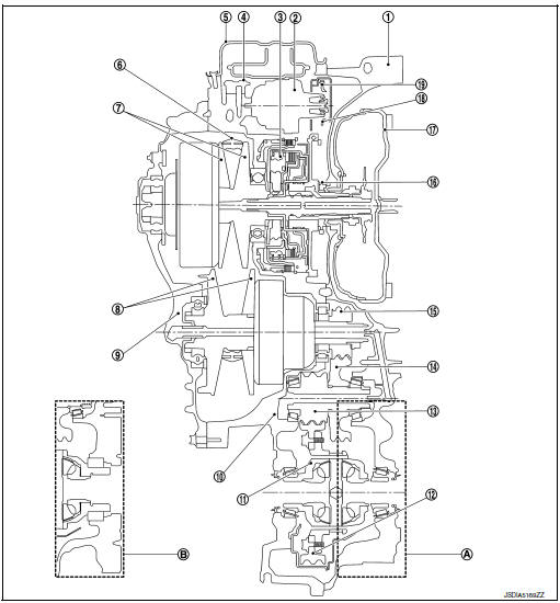
- Converter housing
- Oil pump
- Planetary gear
- Control valve
- Oil pan
- Steel belt
- Primary pulley
- Secondary pulley
- Side cover
- Transaxle case
- Differential case
- Final gear
- Reduction gear
- Idler gear
- Output gear
- Drive sprocket
- Torque converter
- Driven sprocket
- Oil pump chain
- FWD
- AWD
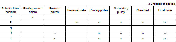
TRANSAXLE : Operation Status
TRANSAXLE : Transaxle Mechanism
TORQUE CONVERTER (WITH LOCK-UP FUNCTION)
In the same way as a conventional A/T, the torque converter is a system that increases the engine torque and transmits the torque to the transaxle. A symmetrical 3-element, 1-stage, 2-phase type is used here.
OIL PUMP
Utilizes a vane-type oil pump that is driven by the engine through the oil pump drive chain in order to increase efficiency of pump discharge volume in low-speed zone and optimize pump discharge volume in high-speed zone. Discharged oil from oil pump is transmitted to control valve. It is used as the oil of primary and secondary pulley operation, the oil of clutch operation, and the lubricant for each part.
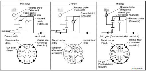
PLANETARY GEAR
- A planetary gear type of forward/reverse selector mechanism is installed between the torque converter and primary pulley.
- The power from the torque converter is input via the input shaft, operating a wet multi-plate clutch by means of hydraulic pressure to switch between forward and reverse driving.
Operation of Planetary gear
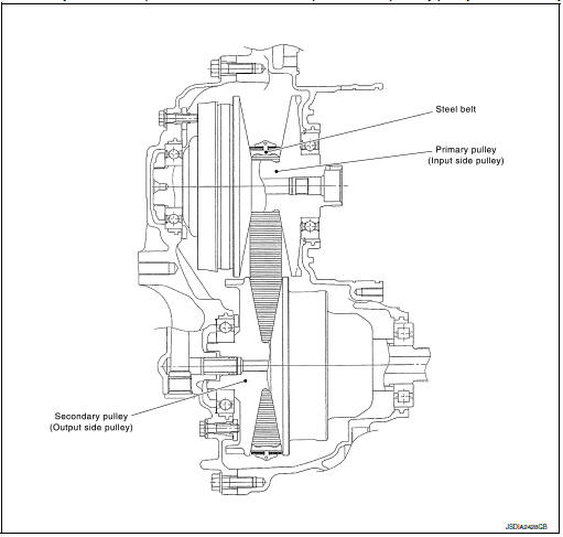
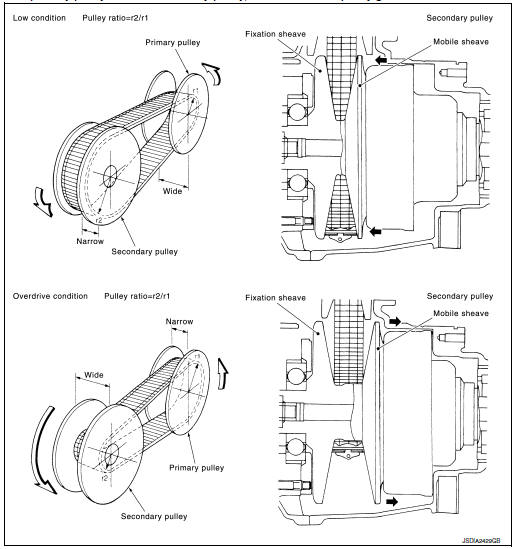
BELT & PULLEY
It is composed of a pair of pulleys (the groove width is changed freely in the axial direction) and the steel belt (the steel plates are placed continuously and the belt is guided with the multilayer steel rings on both sides).
The groove width changes according to wrapping radius of steel belt and pulley from low status to overdrive status continuously with non-step. It is controlled with the oil pressures of primary pulley and secondary pulley.
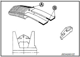
Steel Belt
It is composed of multiple steel plates A and two steel rings B stacked to a several number. The feature of this steel belt transmits power with compression of the steel plate in contrast with transmission of power in pulling with a rubber belt. Friction force is required with the pulley slope to transmit power from the steel plate. The force is generated with the following mechanism: Oil pressure applies to the secondary pulley to nip the plate. ŌćÆThe plate is pushed and extended outward. ŌćÆThe steel ring shows withstands.
ŌćÆPulling force is generated on the steel ring. ŌćÆThe plate of the primary pulley is nipped between the pulley. ŌćÆFriction force is generated between the steel belt and the pulley.
Therefore, responsibilities are divided by the steel plate that transmits the power with compression and the steel ring that maintains necessary friction force. In this way, the tension of the steel ring is distributed on the entire surface and stress variation is limited, resulting in good durability.
Pulley
The primary pulley (input shaft side) and the secondary pulley (output shaft side) have the shaft with slope (fixed cone surface), movable sheave (movable cone surface that can move in the axial direction) and oil pressure chamber at the back of the movable sheave.
The movable sheave slides on the shaft to change the groove width of the pulley. Input signals of engine load (accelerator pedal opening), primary pulley speed and secondary pulley speed change the operation pressures of the primary pulley and the secondary pulley, and controls the pulley groove width.
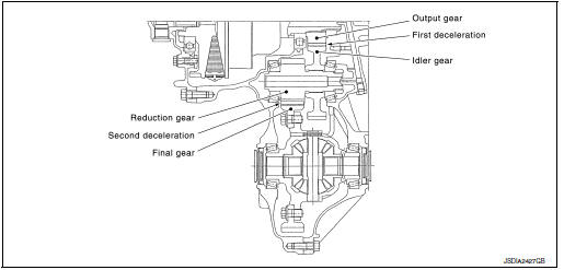
FINAL DRIVE AND DIFFERENTIAL
The deceleration gears are composed of 2 stages: primary deceleration (output gear, idler gear pair) and secondary deceleration (reduction gear, final gear pair). All of these gears are helical gears.
The lubrication oil is the same as the CVT fluid which lubricates the entire transaxle
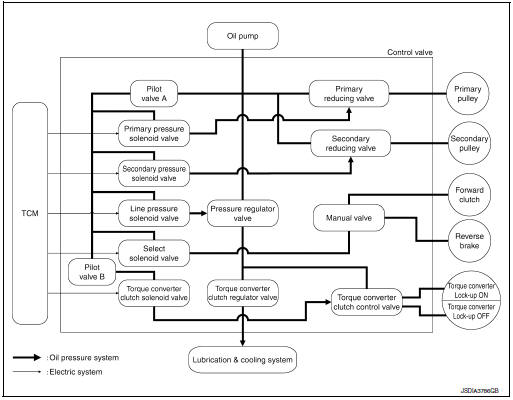
TRANSAXLE : Oil Pressure System
Oil pressure required for operation of the transaxle transmission mechanism is generated by oil pump, oil pressure control valve, solenoid valve, etc.
TRANSAXLE : Component Description
| Part name | Function |
| Torque converter | Increases engine torque and transmits it to the transaxle. |
| Oil pump | Utilizes a vane-type oil pump that is driven by the engine through the oil pump drive chain in order to increase efficiency of pump discharge volume in low-speed zone and optimize pump discharge volume in high-speed zone. Discharged oil from oil pump is transmitted to control valve. It is used as the oil of primary and secondary pulley operation, the oil of clutch operation, and the lubricant for each part. |
| Forward clutch | The forward clutch is wet and multiple plate type clutch that consists of clutch drum, piston, drive plate, and driven plate. It is a clutch to move the vehicle forward by activating piston hydraulically, engaging plates, and directly connecting sun gear and input shaft. |
| Reverse brake | The reverse brake is a wet multiple-plate type brake that consists of transaxle case, piston, drive plate, and driven plate. It is a brake to move the vehicle in reverse by activating piston hydraulically, engaging plates, and fixing planetary gear. |
| Internal gear | The internal gear is directly connected to forward clutch drum. It is a gear that moves the outer edge of pinion planet of planet carrier. It transmits power to move the vehicle in reverse when the planet carrier is fixed. |
| Planet carrier | Composed of a carrier, pinion planet, and pinion shaft. This gear fixes and releases the planet carrier in order to switch between forward and reverse driving. |
| Sun gear | Sun gear is a set part with planet carrier and internal gear. It transmits transmitted force to primary fixed sheave. It rotates in forward or reverse direction according to activation of either forward clutch or reverse brake. |
| Input shaft | The input shaft is directly connected to forward clutch drum and
transmits traction force from torque converter.
In shaft center, there are holes for hydraulic distribution to primary pulley and hydraulic distribution for lockup ON/OFF. |
| Primary pulley | It is composed of a pair of pulleys (the groove width is changed freely in the axial direction) and the steel belt. The groove width changes according to wrapping radius of steel belt and pulley from low status to overdrive status continuously with non-step. It is controlled with the oil pressures of primary pulley and secondary pulley. |
| Secondary pulley | |
| Steel belt | |
| Manual shaft | When the manual shaft is in the P position, the parking rod that is linked to the manual shaft rotates the parking pole. When the parking pole rotates, it engages with the parking gear, fixing the parking gear. As a result, the secondary pulley that is integrated with the parking gear is fixed. |
| Parking rod | |
| Parking pawl | |
| Parking gear | |
| Output gear | The deceleration gears are composed of 2 stages: primary deceleration (output gear, idler gear pair) and secondary deceleration (reduction gear, final gear pair). All of these gears are helical gears. |
| Idler gear | |
| Reduction gear | |
| Differential | |
| Torque converter regulator valve | Adjusts the feed pressure to the torque converter to the optimum pressure corresponding to the driving condition. |
| Pressure regulator valv | Adjusts the discharge pressure from the oil pump to the optimum pressure (line pressure) corresponding to the driving condition. |
| Torque converter clutch control valve | Adjusts the torque converter engage and disengage pressures. |
| Manual valve | Distributes the clutch operation pressure to each circuit according to the selector lever position. |
| Secondary reducing valve | Reduces line pressure and adjusts secondary pressure. |
| Primary reducing valve | Reduces line pressure and adjusts primary pressure. |
| Pilot valve A | Reduces line pressure and adjusts pilot pressure to the solenoid
valves listed below.
|
| Pilot valve B | Reduces pilot pressure and adjusts pilot pressure to the torque converter clutch solenoid valve. |
FLUID COOLER & FLUID WARMER SYSTEM
FLUID COOLER & FLUID WARMER SYSTEM : System Description
CVT FLUID COOLER SCHEMATIC
COMPONENT DESCRIPTION
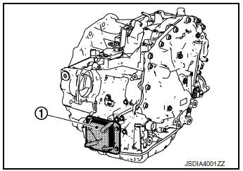
CVT Oil Warmer
- The CVT oil warmer 1 is installed on the front part of transaxle assembly.
- When engine is started while engine and CVT are cold, engine
coolant temperature rises more quickly than CVT fluid temperature.
CVT oil warmer is provided with two circuits for CVT and engine coolant respectively so that warmed engine coolant warms CVT quickly. This helps shorten CVT warming up time, improving fuel economy.
- A cooling effect is obtained when CVT fluid temperature is high.
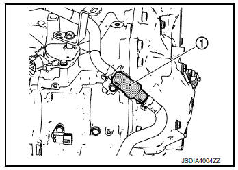
Heater Thermostat
- The heater thermostat 1 is installed on the front part of transaxle assembly.
- The heater thermostat open and close with set temperature.
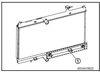
CVT Fluid Cooler (Water Cooling Type)
- The CVT fluid cooler (water cooling type) 1 is installed in the lower part of radiator.
- CVT fluid is cooled by engine coolant to flow through the radiator.
SHIFT LOCK SYSTEM
SHIFT LOCK SYSTEM : System Description
- The shift lock system prevents the select lever from being moved from ŌĆ£PŌĆØ position to other positions due to a driver's improper operation and prevents the occurrence of an abrupt start.
- Shift lock can be released when the following conditions are satisfied.
- Ignition switch is ON.
- Brake pedal is depressed. (Stop lamp switch is ON)
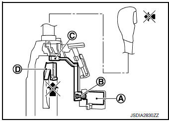
SHIFT LOCK OPERATION AT P POSITION
When brake pedal is not depressed (no selector operation allowed) When the brake pedal is not depressed with the ignition switch ON, the shift lock solenoid A is OFF (not energized) and the solenoid rod B is extended with spring.
The connecting lock lever C is located at the position shown in the figure when the solenoid rod is extended. It prevents the movement of the detent rod D. The selector lever cannot be shifted from the ŌĆ£PŌĆØ position for this reason.
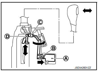
When brake pedal is depressed (selector lever operation allowed) The shift lock solenoid A is turned ON (energized) when the brake pedal is depressed with the ignition switch ON. The solenoid rod B is compressed with the electromagnetic force. The connecting lock lever C rotates when the solenoid rod is compressed. Therefore, the detent rod D can be moved. The selector lever can be shifted to other positions for this reason.
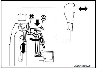
FORCIBLE RELEASE OF SHIFT LOCK
- When battery voltage decreases or an electrical/mechanical malfunction occurs in the shift lock system, the selector lever cannot be operated in ŌĆ£PŌĆØ position. When shift lock release rod A is pressed in this state, lock lever B is forcibly rotated, and then it becomes possible to release shift lock.
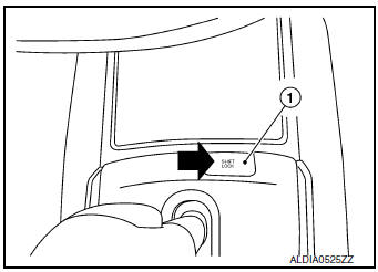
- To release the shift lock forcibly and shift the selector lever from ŌĆ£PŌĆØ position to other positions, follow the steps below.
- Turn ignition switch OFF.
- Apply parking brake.
- Press the shift lock release button 1 with suitable tool.
- Press and hold the selector lever knob button and move the selector lever from ŌĆ£PŌĆØ position to other positions while press the shift lock release button.
KEY LOCK SYSTEM
KEY LOCK SYSTEM : System Description
KEY LOCK MECHANISM
The key is not set to LOCK when the selector lever is not selected to P position. This prevents the key from being removed from the key cylinder.
Key lock status
The slider B in the key cylinder A is moved to the left side of the figure when the selector lever is in any position other than ŌĆ£PŌĆØ position.
The rotator D that rotates together with the key C cannot be rotated for this reason. The key cannot be removed from the key cylinder because it cannot be turned to LOCK .
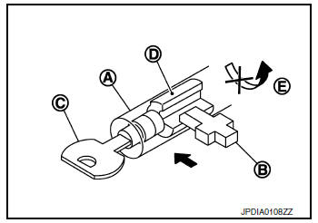
Key unlock status
The slider B in the key cylinder A is moved to the right side of the figure when the selector lever is in ŌĆ£PŌĆØ position and the finger is removed from the selector button. The rotator C can be rotated for this reason. The key D can be removed from the key cylinder because it can be turned to LOCK E.
 Component parts
CVT CONTROL SYSTEM
CVT CONTROL SYSTEM : Component Parts Location
Engine room, LH
Transaxle assembly
No.
Component
Function
1
Combination meter
Mainly tra ...
 System
CVT CONTROL SYSTEM
CVT CONTROL SYSTEM : System Description
SYSTEM DIAGRAM
MAIN CONTROL CONTENTS OF TCM
Controls
Reference
Line pressure control
TM-36, "LINE PRESSURE ...
Other materials:
Cold weather driving
Freeing a frozen door lock
To prevent a door lock from freezing, apply deicer
through the key hole. If the lock becomes
frozen, heat the key before inserting it into the key
hole, or use the NISSAN Intelligent Key®.
Antifreeze
In the winter when it is anticipated that the temperature
will dr ...
Operating range
Operating range
The Intelligent Key functions can only be used
when the Intelligent Key is within the specified
operating range from the request switch 1 .
When the Intelligent Key battery is discharged or
strong radio waves are present near the operating
location, the Intelligent Key op ...
Precaution
Precaution for Supplemental Restraint System (SRS) "AIR BAG" and "SEAT
BELT
PRE-TENSIONER"
The Supplemental Restraint System such as ŌĆ£AIR BAGŌĆØ and ŌĆ£SEAT BELT PRE-TENSIONERŌĆØ,
used along
with a front seat belt, helps to reduce the risk or severity of injury to the
...
