Nissan Rogue Service Manual: Component parts
Component Parts Location
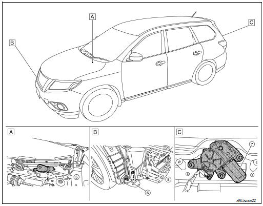
- View of cowl area (with cowl top cover removed)
- RH front of vehicle (with front bumper fascia removed)
- View with back door finisher removed
|
No. |
Component |
Function |
| 1 | Combination switch (Wiper and washer switch) | Refer to WW-8, "FRONT WIPER AND WASHER SYSTEM : System Description".
Refer to BCS-76, "Removal and Installation". |
| 2 | Combination meter | Transmits the vehicle speed signal to BCM via CAN communication. |
| 3 | IPDM E/R |
Refer to WW-6, "Component Parts Location" |
| 4 | BCM |
Refer to WW-6, "Component Parts Location". |
| 5 | Front wiper motor | Refer to WW-7, "Front wiper motor". |
| 6 | Front and rear washer motor | Refer to WW-7, "Washer pump". |
| 7 | Rear wiper motor | Refer to WW-7, "Rear wiper motor". |
| 8 | Washer Fluid Level Switch | Transmits the washer fluid level switch signal to the combination meter. |
Front wiper motor
- Controls front wiper operation with IPDM E/R control.
- Transmits front wiper stop position signal to IPDM E/R.
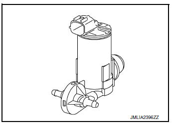
Washer pump
- Washer fluid is sprayed according to washer switch states.
- Switching between front washer and rear washer is performed according to the voltage polarity change to washer pump.
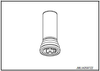
Washer fluid level switch
Detects that washer fluid level is low and transmits washer fluid level switch signal to combination meter.
Rear wiper motor
- Controls rear wiper operation with BCM control.
- Transmits rear wiper stop position signal to BCM.

 System
FRONT WIPER AND WASHER SYSTEM
FRONT WIPER AND WASHER SYSTEM : System Diagram
FRONT WIPER AND WASHER SYSTEM : System Description
OUTLINE
FRONT WIPER CONTROL (BASIC)
BCM detects the co ...
Other materials:
DTC/circuit diagnosis
U0428 STEERING ANGLE SENSOR
DTC Logic
DTC DETECTION LOGIC
CONSULT Display
DTC Detection Condition
Possible Cause
ST ANG SEN CALIB
[U0428]
Predictive course line center position adjustment
of steering angle sensor is incomplete.
Adjust predictive cours ...
B00D5 front passenger air bag off indicator
DTC Logic
DTC DETECTION LOGIC
With CONSULT
CONSULT name
DTC
DTC detecting condition
Repair order
PASSENGER AIRBAG INDICATOR CIRCUIT
[FAIL]
B00D5
Front passenger air bag OFF indicator
is malfunctioning.
Refer to SRC-91, "Diagnosis Proced ...
Preparation
Special Service Tool
The actual shape of the tools may differ from those illustrated here.
Tool number
(TechMate No.)
Tool name
Description
—
(J-39570)
Chassis Ear
Locating the noise
—
(J-50397)
NISSAN Squeak and Rattle Kit
...
