Nissan Rogue Service Manual: Basic inspection
DIAGNOSIS AND REPAIR WORK FLOW
Work Flow
OVERALL SEQUENCE
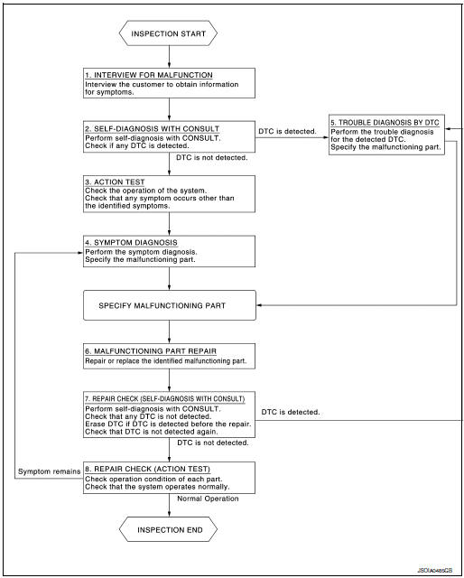
DETAILED FLOW
1.INTERVIEW FOR MALFUNCTION
It is also important to clarify the customer concerns before starting the inspection. Interview the customer about the concerns carefully and understand the symptoms fully.
NOTE: The customers are not professionals. Never assume that “maybe the customer means···” or “maybe the customer mentioned this symptom”. >> GO TO 2.
2.SELF-DIAGNOSIS WITH CONSULT
- Perform “All DTC Reading” with CONSULT.
- Check if the DTC is detected on the “Self-Diagnostic Results” of following:
- “DISTANCE SENSOR”
- “AROUND VIEW MONITOR”
Is any DTC detected? YES >> GO TO 5.
NO >> GO TO 3.
3.ACTION TEST
Perform the following system action test to check the system operation:
- LDW refer to DAS-80, "LDW : Description".
- BSW refer to DAS-81, "BSW : Description".
- MOD refer to DAS-82, "MOD : Description".
Check if any other malfunctions occur.
>> GO TO 4.
4.SYMPTOM DIAGNOSIS
Perform the applicable diagnosis according to the diagnosis chart by symptom. Refer to DAS-152, "Symptom Table".
>> GO TO 6.
5.TROUBLE DIAGNOSIS BY DTC
- Check the DTC in the “Self-Diagnostic Results”.
- Perform trouble diagnosis for the detected DTC following:
- “DISTANCE SENSOR”: Refer to DAS-49, "DTC Index".
- “AROUND VIEW MONITOR”: Refer to DAS-47, "DTC Index".
>> GO TO 6.
6.MALFUNCTIONING PART REPAIR
Repair or replace the identified malfunctioning parts.
>> GO TO 7.
7.REPAIR CHECK (SELF-DIAGNOSIS WITH CONSULT)
- Erases self-diagnosis results.
- Perform “All DTC Reading” again after repairing or replacing the specific items.
- Check if any DTC is detected in self-diagnosis results of following:
- “DISTANCE SENSOR”
- “AROUND VIEW MONITOR”
Is any DTC detected? YES >> GO TO 5.
NO >> GO TO 8.
8.REPAIR CHECK (ACTION TEST)
Perform the following system action test. Check that the malfunction symptom is solved or no other symptoms occur.
Is there a malfunction symptom?
YES >> GO TO 4.
NO >> Inspection End.
PRE-INSPECTION FOR DIAGNOSIS
Inspection Procedure
1.CHECK REAR VIEW CAMERA LENS
Is the rear view camera lens contaminated with foreign materials? YES >> Clean rear view camera lens.
NO >> GO TO 2.
2.CHECK REAR VIEW CAMERA INSTALLATION CONDITION
Check rear view camera installation condition (e.g. position, looseness, bent in back door).
Is it properly installed? YES >> Inspection End.
NO >> Install rear view camera properly, and perform rear view camera calibration. Refer to DAS-89, "Description".
REAR VIEW CAMERA WASHER/AIR BLOWER FUNCTION INSPECTION
Inspection Procedure
1.CHECK REAR VIEW CAMERA WASHER/AIR BLOWER FUNCTION
- Start the engine.
- Select the “Active Test” item “AIR&WASH ACTIVE” of “AVM” with CONSULT.
NOTE: Before function check, perform the following items:
- Fill with washer fluid.
- Perform “Active Test” item “WASH ACTIVE” of “AVM” with CONSULT for 4 seconds.
- While operating the test item, check the operation.
Is it properly operated? Washer fluid ejects 4 - 6 times. (Normal function)>>Inspection End.
Washer fluid ejects 7 times or more.>>Properly install or replace air tube.
Washer fluid ejects only once>> Properly install or replace air tube.
Washer fluid does not eject>>Properly install washer tube or replace washer tube and check valve.
ADDITIONAL SERVICE WHEN REPLACING DISTANCE SENSOR
Description
Always perform the following after removing and installing or replacing the Distance sensor:
- Distance sensor initial vertical alignment
- Distance sensor alignment
- CAUTION: The system does not operate normally unless the Distance sensor is aligned properly.
Work Procedure
1.DISTANCE SENSOR INITIAL VERTICAL ALIGNMENT
Perform the distance sensor initial vertical alignment. Refer to DAS-70, "Description".
>> GO TO 2.
2.DISTANCE SENSOR ALIGNMENT
Perform the distance sensor alignment. Refer to DAS-72, "Description".
>> Work End.
DISTANCE SENSOR INITIAL VERTICAL ALIGNMENT
Description
WARNING: Radio waves could adversely affect electric medical equipment. Those who use a pacemaker should contact the electric medical equipment manufacturer for the possible influences before use.
OUTLINE OF DISTANCE SENSOR INITIAL ALIGNMENT PROCEDURE
- Always perform the Distance sensor initial vertical alignment after removing and installing or replacing the Distance sensor.
CAUTION: The system does not operate normally unless the Distance sensor is aligned properly.
- Required tools, refer to DAS-70, "Required Tools".
- Preparation, refer to DAS-70, "Preparation".
- Distance sensor initial vertical alignment, refer to DAS-71, "Distance Sensor Initial Vertical Alignment".
CAUTIONARY POINT FOR DISTANCE SENSOR ALIGNMENT PROCEDURE
CAUTION:
- For Distance sensor alignment procedure, choose a level location with a few feet of working space in front and surrounding the vehicle.
- Vehicle must be stationary and unoccupied during the whole alignment procedure.
- Never enter the vehicle during distance sensor alignment.
- For proper system operation and adjustment, all vehicle wheels must be the original factory size.
The Distance sensor requires alignment whenever the Distance sensor is removed and reinstalled and whenever front end structural repairs are performed. Distance sensor alignment consists of performing the mechanical vertical alignment (Distance sensor initial vertical alignment) described in the following procedure, followed by the electronic horizontal alignment (Distance sensor alignment) that is performed using CONSULT and the appropriate special service tools.
Required Tools
The following tool is necessary to perform the Distance sensor initial vertical alignment:
- Carpenters level.
Preparation
1.PREPARATION FOR DISTANCE SENSOR INITIAL VERTICAL ALIGNMENT PROCEDURE
- Verify correct vehicle suspension height. Refer to WT-65, "Wheel".
- Repair or replace any damaged body components.
- Verify proper tire inflation pressures. Refer to WT-65, "Tire Air Pressure".
- Remove any accumulations of mud, snow or ice from the vehicle underbody.
- Verify that there is no load in the vehicle (cargo or passenger).
- Place the vehicle on a known level horizontal surface such as a wheel or frame alignment rack to achieve satisfactory sensor vertical alignment results.
- Remove front fascia. Refer to EXT-17, "Removal and Installation".
>> Refer to DAS-71, "Distance Sensor Initial Vertical Alignment".
Distance Sensor Initial Vertical Alignment
NOTE: The Distance sensor initial vertical alignment procedure must be performed anytime the Distance sensor is removed and reinstalled.
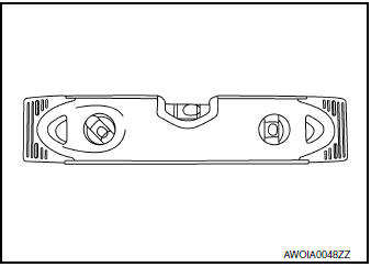
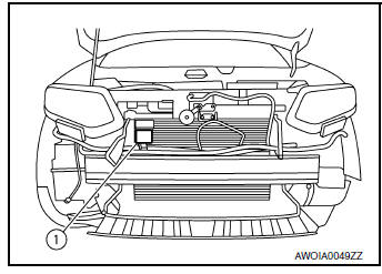
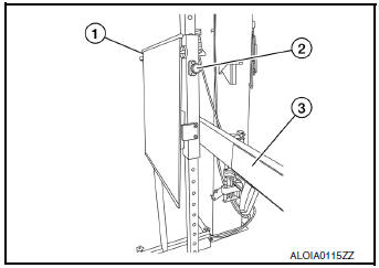
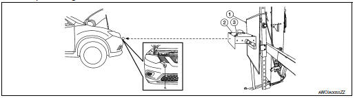
- The Distance sensor (1) is located near the right front head lamp behind the front bumper fascia.
- Place the carpenters level (2) against the face of the Distance sensor (1).
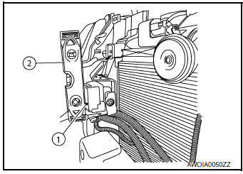
- Turn the Distance sensor adjustment screw (3) to level the sensor.
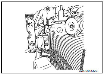
- Insure the Distance sensor electrical connector located on the bottom of the sensor is connected.
- Reinstall the front bumper fascia.
- Perform the Distance sensor alignment procedure. Refer to DAS-72, "Description".
DISTANCE SENSOR ALIGNMENT
Description
WARNING: Radio waves could adversely affect electric medical equipment. Those who use a pacemaker should contact the electric medical equipment manufacturer for the possible influences before use.
OUTLINE OF RADAR ALIGNMENT PROCEDURE
- A 4-wheel vehicle alignment must be performed before proceeding with radar alignment procedure.
- Always perform the radar alignment after removing and installing or replacing the Distance sensor.
- If the Distance sensor was removed and installed or replaced, first perform Distance Sensor Initial Vertical Alignment, refer to DAS-70, "Description".
CAUTION: The system does not operate normally unless the Distance sensor is aligned properly.
- Required tools, refer to DAS-72, "Required Tools".
- Preparation, refer to DAS-74, "Preparation".
- Vehicle set up, refer to DAS-74, "Vehicle Set Up".
- Setting the Distance sensor target board, refer to DAS-76, "Setting The Distance Sensor Target Board".
- Distance sensor adjustment, refer to DAS-77, "Distance Sensor Adjustment".
CAUTIONARY POINT FOR RADAR ALIGNMENT PROCEDURE
CAUTION:
- For radar alignment procedure, choose a level location with a few feet of working space in front and surrounding the vehicle.
- Vehicle must be stationary and unoccupied during the whole alignment procedure.
- Any slight vibration during the alignment procedure can cause the test to fail. If this happens, you will have to restart the alignment process.
- The ignition switch must be in the ON position.
- The battery voltage must not fall below 12 volts during the whole alignment procedure. Failure to maintain adequate battery voltage will cause the test to fail. If this happens, you will have to restart the alignment process.
- The Distance sensor target board must be set in front of the vehicle facing the sensor.
- Adjust the radar alignment with CONSULT. (The radar alignment procedure cannot be adjusted without CONSULT.)
- Never enter the vehicle during radar alignment.
- Never block the area between the radar and the Distance sensor target board at any time during the alignment process.
- Never break the laser beam between the laser assembly and front Distance sensor target board or rear reflector at any time during alignment.
- Accurate steering wheel setting is crucial. Once set, do not disturb the steering wheel for the remainder of the alignment procedure.
- To avoid physical damage, the Distance sensor adjustment screw must not be forced to either clockwise or counter-clockwise limit. For proper adjustment procedure, follow the directions of the CONSULT exactly as instructed.
- For proper system operation and adjustment, all vehicle wheels must be of the same size.
Required Tools
- Distance sensor alignment kit 1-20-2721-1-IF in addition to one of the following: a) Hunter self-centering wheel adapter (Hunter wheel alignment tool) b) Special Service Tool kit 1-20-2722-1-IF (kit SCA W/Tire Clamp-ICC Aiming)
- Distance sensor alignment kit attachment board J-50808
The following Distance sensor alignment kit (1-20-2721-1-IF) and Distance sensor alignment kit attachment board (target board) (J-50808) are necessary to perform the Distance sensor alignment:
- Distance sensor alignment kit attachment board (target board) (1).
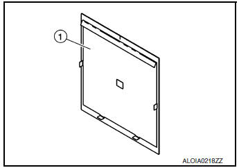
- Distance sensor target board (1).
- Hunter self-centering wheel adapter (1) [shown with laser assembly
(2) installed] (Hunter alignment rack head may be substituted).
NOTE: Dealers that are not equipped with a Hunter self-centering wheel adapter will require the following kit: Part No. 1-20-2722-1-IF (kit SCA W/Tire Clamp-Distance Sensor Aiming)
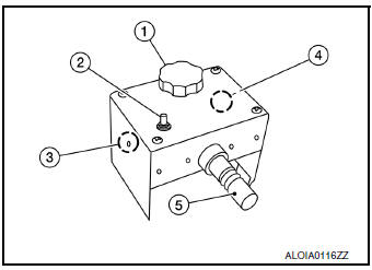
- Laser assembly (with bi-directional laser beam) as shown in the illustration.
- Tightening knob (1)
- Power ON/OFF button (2)
- Front laser beam opening (3)
- Rear laser beam opening (4)
- Attaching shaft (5)
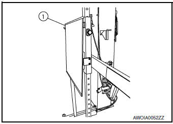
- Stationary target as shown in the illustration.
- Stationary target (1)
- Laser signal reception plate (2)
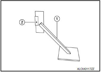
- Distance chain (not shown).
Preparation
1.ADVANCE PREPARATION FOR RADAR ALIGNMENT PROCEDURE
- Adjust all tire pressures to the specified value.
- Empty the vehicle. (Remove any luggage from the passenger compartment, luggage room, etc.)
- Shift the selector lever to “P” position, and release the parking brake.
- Fully fill the fuel tank, and then check that the coolant and oils are filled up to correct level.
- Clean off the right front side of the fascia in front of the
Distance sensor.
NOTE: The Distance sensor is located behind the fascia and it is not exposed to the elements. Therefore it should not require any cleaning.
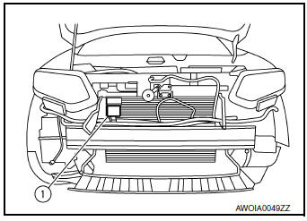
1 : Distance sensor
>> Refer to DAS-74, "Vehicle Set Up".
Vehicle Set Up
DESCRIPTION
Accurate adjustment of the radar alignment requires that the Distance sensor target board, wheel adapter, laser assembly, and stationary target be properly positioned.
CAUTION: If the radar alignment is adjusted with the Distance sensor target board, wheel adapter, laser assembly, or stationary target in the incorrect position, the Distance system will not function properly or the alignment procedure may not be completed successfully.
1.PREPOSITION TARGET BOARD
NOTE:
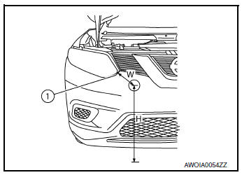
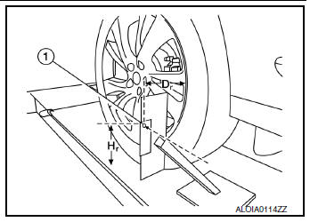
- The center of the distance sensor (A).
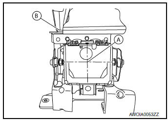
B : Up-down direction adjusting screw
- To locate the center of the distance sensor (A) easily, on a flat level surface measure 27 in (685 mm) (H) up from the floor, and 7 in (178 mm) (W) to the right from the point of the right front head lamp (1) when viewed from the front of the vehicle.
- Initial distance sensor target board setting must be in the center position.
- Position the distance sensor target board in front facing the right front side of the vehicle:
- Using the full length of the supplied chain for distance, place the marked center of the distance sensor target board (1) 1375 mm (54.1 in.) ± 625 mm(24.6 in) facing the distance sensor.
- Adjust the height of the distance sensor target board using the adjustable nut (2) to achieve the proper height. The up/down tolerance is ± 80 mm (3.15 in).
- Adjust the distance sensor target board lateral position aligning the marked center of the board horizontally with the center of the distance sensor front. The right/left tolerance is ± 80 mm (3.15 in).
- Extend the machined arm of the distance sensor target board exposing the reflective surface (3) to the right front side of the vehicle.
- Place one side of the laser assembly (2) flush against the center of the distance sensor target board (1) to assist in the positioning.
- Turn the laser assembly ON (3) allowing the laser beam to emit through the opening of the laser assembly toward the center of the distance sensor.
- Move the distance sensor target board (1) as necessary so that center of distance sensor target board aligns with center of distance sensor.
- Turn the laser assembly OFF when done.
Are you using Hunter alignment equipment? YES >> Refer to Hunter’s equipment instructions for complete vehicle set up and distance sensor target board setting. Then, refer to DAS-77, "Distance Sensor Adjustment".
NO >> GO TO 2.
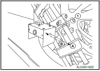
2.INSTALLING LASER ASSEMBLY
NOTE:
- Insure the steering wheel is positioned in the center straight forward position.
- Insure all 4 vehicle wheels do not contain any physical damage.
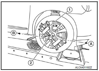
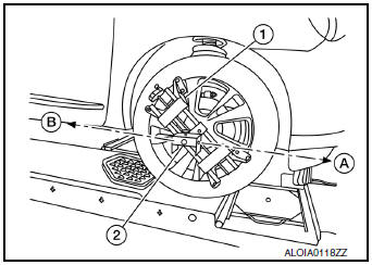
- Install the wheel adapter (1) on the right front wheel.
- Mount the laser assembly (2) to the wheel adapter (1) as shown in the figure.
NOTE: When the power switch is turned ON, the front laser signal (A) will be emitted toward the front distance sensor target board, and the rear laser signal (B) will be emitted toward the rear of the vehicle. >> GO TO 3.
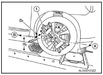
3.SETTING UP STATIONARY TARGET
- Place the stationary target next to the right rear tire as shown in the figure.
- Turn the laser assembly ON allowing the laser beam to be emitted through the front and rear laser assembly openings.
- Measure and record the distance (Dr) between the edge of the right rear wheel and the laser beam (1) on the stationary target (horizontal line).
- Measure and record the height (Hr) between the laser beam (1) on the stationary target and ground level (vertical line).
- Measure and record the distance (Df) between the edge of the right front wheel and the laser beam signal/opening (1) on the laser assembly (horizontal line).
- Measure and record the height (Hf) between the laser beam signal/ opening (1) on the laser assembly and ground level (vertical line).
NOTE:
- Horizontal adjustment [front distance (Df) and rear distance (Dr)] is accomplished by slowly turning the steering wheel until the 2 distances are the same.
- Vertical adjustment [front height (Hf) and rear height (Hr)] is accomplished by rotating the laser assembly around its axis until the two heights are the same.
- Directional arrows (A) and (B) are shown to illustrate the direction of the laser assembly beams.
- Adjust laser beam as necessary until the two distances match and
the two heights match.
NOTE: You will have to verify both horizontal and vertical adjustments anytime one adjustment is made.
>> Refer to DAS-76, "Setting The Distance Sensor Target Board".
Setting The Distance Sensor Target Board
DESCRIPTION
Accurate adjustment of the radar alignment requires that the distance sensor target board be accurately positioned.
CAUTION: If the radar alignment is adjusted with the distance sensor target board in the incorrect position, the distance system will not function properly or the alignment procedure may not be completed successfully.
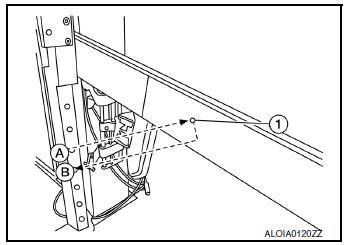
1.DISTANCE SENSOR TARGET BOARD FINAL SETTING
- With the distance sensor target board arm extended, the laser
beam (1) emitted by the laser assembly (A) will be reflected
back (B) toward the laser assembly.
NOTE: When adjusted properly, reflected laser beam (B) must align with emitted laser beam (A) and the two laser beams will be seen as one.
- Rotate the distance sensor target board to achieve the necessary horizontal adjustment.
- Adjust the distance sensor target board leveling screws to achieve the necessary vertical adjustment.
- The figure shown illustrates the laser beam (A) emitted by the laser assembly (1) and its reflection (B) off of the distance sensor target board arm.
>> GO TO 2.
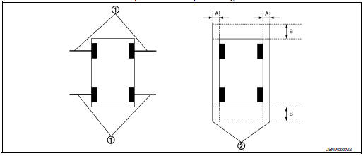
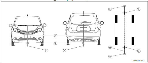
2.CHECK THE POSITION OF THE DISTANCE SENSOR TARGET BOARD
Do not place anything other than the distance sensor target board in the space shown in front of the vehicle (view from top).
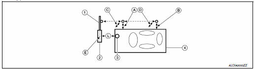
- Distance sensor target board arm
- Distance sensor target board
- Distance sensor
- Vehicle
- Distance between front wheel and laser beam (Df)
- Distance between rear wheel and laser beam (Dr)
- Height between front laser beam and ground (Hf)
- Height between rear laser beam and ground (Hr)
- Distance sensor target board center position (Position 2)
- 750 - 2000 mm (29.5 - 78.7 in)
>> Refer to DAS-77, "Distance Sensor Adjustment".
Distance Sensor Adjustment
DESCRIPTION
The radar alignment is performed automatically with CONSULT.
CAUTION: Perform all necessary work for radar alignment until the adjustment completes as shown in the procedure.
If the procedure does not complete, the FCW system is inoperable.
1.PERFORM RADAR ALIGNMENT
- Start the engine.
- Connect CONSULT and select “Work support” of “LASER/RADAR”.
- Select “MILLIWAVE RADAR ADJUST” after the “Work support” screen is displayed.
NOTE: Confirm the following items;
- The target should be accurately placed.
- The vehicle should be stopped.
- Select “Start” after the “MILLIWAVE RADAR ADJUST” screen is
displayed.
CAUTION: Never select “Start” when the target is not accurately placed.
- Select “Start” after the preparation information is displayed.
- Select “Next” after the “Starting alignment.” screen is displayed.
NOTE: If the radar is in alignment at this time, “Alignment in progress” is displayed. It may take several 10s of seconds until the result is displayed.
- Confirm the displayed item.
- “Alignment completed.”: Go to 8.
- Except “Alignment completed.”: Perform the following services.
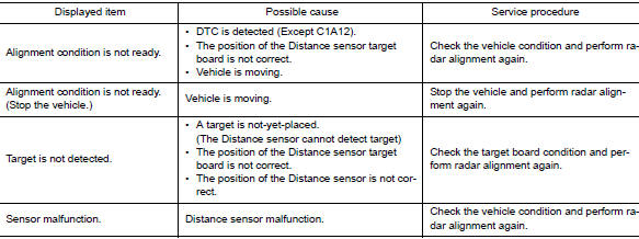
NOTE: Replace Distance sensor if “Sensor malfunction.” is repeatedly indicated.
- Confirm displayed value.
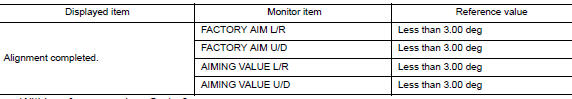
- Within reference value: Go to 9.
- Outside of reference value: Check the target board condition and perform radar alignment again.
NOTE:
- Check the condition of the Distance sensor installation.
- Check the vehicle for damage.
- Replace Distance sensor if it is outside the reference value, even when Distance sensor installation is installed normally and the vehicle is not damaged.
- Select “OK” after the “No error detected.” is displayed.
- Select “OK” after the “End of alignment.” is displayed.
CAUTION: Once “MILLIWAVE RADAR ADJUST” is started with CONSULT, always continue the work until the horizontal radar alignment is completed successfully. If the job is stopped midway, the radar alignment is not adjusted and the FCW system cannot operate.
>> RADAR ALIGNMENT END
ACTION TEST
LDW
LDW : Description
- Perform action test to verify the customer's concern.
- Perform action test and check the system operation after system diagnosis.
WARNING: Be careful of traffic conditions and safety around the vehicle when performing road test.
CAUTION:
- Fully understand the following items well before the road test;
- Precautions: Refer to DAS-9, "Precautions for Driver Assistance Systems".
- System description for LDW: Refer to DAS-16, "LDW : System Description".
- System description for BSW: Refer to DAS-20, "BSW : System Description".
- System description for MOD: Refer to DAS-26, "MOD : System Description".
- Handling precaution: Refer to DAS-36, "Precautions for Lane Departure Warning".
LDW : Inspection Procedure
WARNING: Be careful of traffic conditions and safety around the vehicle when performing road test.
CAUTION:
- Fully understand the following items well before the road test;
- Precautions: Refer to DAS-9, "Precautions for Driver Assistance Systems".
- System description for LDW: Refer to DAS-16, "LDW : System Description".
- System description for BSW: Refer to DAS-20, "BSW : System Description".
- System description for MOD: Refer to DAS-26, "MOD : System Description".
- Handling precaution: Refer to DAS-36, "Precautions for Lane Departure Warning".
1.CHECK LDW SYSTEM SETTING
- Start the engine.
- Check that the LDW system setting can be enabled/disabled on the vehicle information display.
- Turn OFF the ignition switch and wait for 30 seconds or more.
- Check that the previous setting is saved when the engine starts again.
>> GO TO 2.
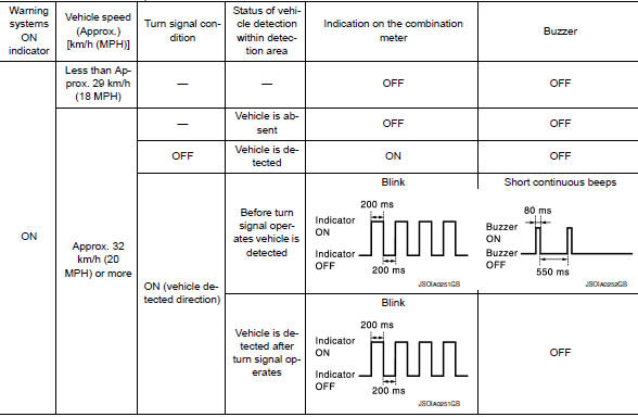
2.ACTION TEST FOR LDW
- Enable the setting of the LDW system on the vehicle information display.
- Turn warning systems switch ON (warning systems ON indicator is ON).
- Check the LDW operation according to the following table.
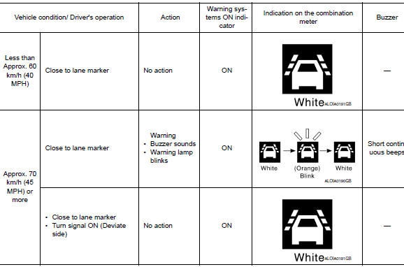
NOTE: After the operating conditions of warning are satisfied, the warning continues until the vehicle speed reaches approximately 60 km/h (40 MPH). Refer to DAS-16, "LDW : System Description".
>> Inspection End.
BSW
BSW : Description
- Perform action test to verify the customer's concern.
- Perform action test and check the system operation after system diagnosis.
WARNING: Be careful of traffic conditions and safety around the vehicle when performing road test.
CAUTION:
- Fully understand the following items well before the road test;
- Precautions: Refer to DAS-9, "Precautions for Driver Assistance Systems".
- System description for LDW: Refer to DAS-20, "BSW : System Description".
- System description for BSW: Refer to DAS-20, "BSW : System Description".
- System description for MOD: Refer to DAS-26, "MOD : System Description".
- Handling precaution: Refer to DAS-37, "Precautions for Blind Spot Warning".
BSW : Inspection Procedure
WARNING: Be careful of traffic conditions and safety around the vehicle when performing road test.
CAUTION:
- Fully understand the following items well before the road test;
- Precautions: Refer to DAS-9, "Precautions for Driver Assistance Systems".
- System description for LDW: Refer to DAS-16, "LDW : System Description".
- System description for BSW: Refer to DAS-20, "BSW : System Description".
- System description for MOD: Refer to DAS-26, "MOD : System Description".
- Handling precaution: Refer to DAS-37, "Precautions for Blind Spot Warning".
1.CHECK BSW SYSTEM SETTING
- Start the engine.
- Check that the BSW system setting can be enabled/disabled on the vehicle information display.
- Turn OFF the ignition switch and wait for 30 seconds or more.
- Check that the previous setting is saved when the engine starts again.
>> GO TO 2.
2.ACTION TEST FOR BSW
- Enable the setting of the BSW system on the vehicle information display.
- Turn warning systems switch ON (warning systems ON indicator is ON).
- Check the BSW operation according to the following table.
Vehicle condition/Driver’s operation
NOTE: After the operating conditions of warning are satisfied, the warning continues until the vehicle speed reaches approximately 60 km/h (40 MPH). Refer to DAS-20, "BSW : System Description".
>> Inspection End.
MOD
MOD : Description
- Perform action test to verify the customer's concern.
- Perform action test and check the system operation after system diagnosis.
WARNING: Be careful of traffic conditions and safety around the vehicle when performing road test.
CAUTION:
- Fully understand the following items well before the road test;
- Precautions: Refer to DAS-9, "Precautions for Driver Assistance Systems".
- System description for LDW: Refer to DAS-16, "LDW : System Description".
- System description for BSW: Refer to DAS-20, "BSW : System Description".
- System description for MOD: Refer to DAS-26, "MOD : System Description".
- Handling precaution: Refer to DAS-37, "Precautions for Moving Objects Detection".
MOD : Inspection Procedure
WARNING: Be careful of traffic conditions and safety around the vehicle when performing road test.
CAUTION:
- Fully understand the following items well before the road test;
- Precautions: Refer to DAS-9, "Precautions for Driver Assistance Systems".
- System description for LDW: Refer to DAS-16, "LDW : System Description".
- System description for BSW: Refer to DAS-20, "BSW : System Description".
- System description for MOD: Refer to DAS-26, "MOD : System Description".
- Handling precaution: Refer to DAS-37, "Precautions for Moving Objects Detection".
1.CHECK MOD SYSTEM SETTING
- Start the engine.
- Check that the MOD system setting can be enabled/disabled on the vehicle information display.
- Turn OFF the ignition switch and wait for 30 seconds or more.
- Check that the previous setting is saved when the engine starts again.
>> GO TO 2.
2.ACTION TEST FOR MOD
- Enable the setting of the MOD system on the vehicle information display.
- Turn warning systems switch ON (warning systems ON indicator is ON).
- Check the MOD operation according to the following table.
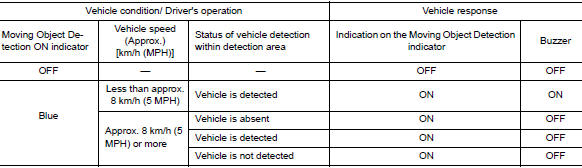
NOTE: After the operating conditions of warning are satisfied, the warning continues until the vehicle reaches a higher speed. Refer to DAS-26, "MOD : System Description". >> Inspection End.
ADDITIONAL SERVICE WHEN REPLACING AROUND VIEW MONITOR CONTROL UNIT
Description
BEFORE REPLACEMENT
When replacing around view monitor control unit, save or print current vehicle specification with CONSULT configuration before replacement.
NOTE: If “Before Replace ECU” cannot be used, use the “After Replace ECU” or “Manual Configuration” after replacing around view monitor control unit.
AFTER REPLACEMENT
CAUTION: When replacing around view monitor control unit, you must perform “After Replace ECU” with CONSULT.
- Complete the procedure of “After Replace ECU” in order.
- If you set incorrect “After Replace ECU”, incidents might occur.
- Configuration is different for each vehicle model. Confirm configuration of each vehicle model.
Work Procedure
1.SAVING VEHICLE SPECIFICATION
 -CONSULT
Enter “Re/Programming, Configuration” and perform “Before Replace ECU” to save or print current vehicle specification.
NOTE: If “Before Replace ECU” cannot be used, use the “After Replace ECU” or “Manual Configuration” after replacing around view monitor control unit.
>> GO TO 2.
2.REPLACE AROUND VIEW MONITOR CONTROL UNIT
Replace around view monitor control unit. Refer to DAS-163, "Removal and Installation".
>> GO TO 3.
3.WRITING VEHICLE SPECIFICATION
 CONSULT
- Enter "Re/Programming, Configuration".
- If “Before Replace ECU” operation was performed, automatically an "Operation Log Selection" screen will be displayed. Select the applicable file from the "Saved Data List" and press “Confirm” to write vehicle specification. Refer to DAS-86, "Work Procedure".
- If “Before Replace ECU” operation was not performed, select "After Replace ECU" or "Manual Configuration" to write vehicle specification. Refer to DAS-86, "Work Procedure".
>> GO TO 4.
4.REAR VIEW CAMERA CALIBRATION
Perform rear view camera calibration. Refer to DAS-89, "Description".
>> GO TO 5.
5.AROUND VIEW MONITOR CALIBRATION
Perform around view monitor calibration. Refer to DAS-93, "Description".
>> GO TO 6.
6.OPERATION CHECK
Check that the operation of the around view monitor control unit and camera images (fixed guide lines and predictive course lines) are normal.
>> Work End.
CONFIGURATION (AROUND VIEW MONITOR CONTROL UNIT)
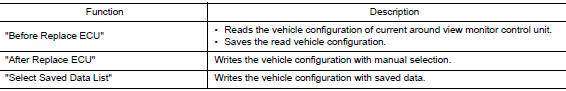
Description
Vehicle specification needs to be written with CONSULT because it is not written after replacing around view monitor control unit.
Configuration has three functions as follows:
CAUTION:
- When replacing around view monitor control unit, you must perform “Select Saved Data List” or "After Replace ECU" with CONSULT.
- Complete the procedure of “Select Saved Data List” or "After Replace ECU" in order.
- If you set incorrect “Select Saved Data List” or "After Replace ECU", incidents might occur.
- Configuration is different for each vehicle model. Confirm configuration of each vehicle model.
- Never perform “Select Saved Data List” or "After Replace ECU" except for new around view monitor control unit.
Work Procedure
1.WRITING MODE SELECTION
CONSULT
Select “Reprogramming, Configuration” of around view monitor control unit.
When writing saved data>>GO TO 2.
When writing manually>>GO TO 3.
2.PERFORM “SAVED DATA LIST”
CONSULT
Automatically “Operation Log Selection” window will display if “Before Replace ECU” was performed. Select applicable file from the “Save Data List” and press “Confirm”.
>> Work End.
3.PERFORM “AFTER REPLACE ECU” OR “MANUAL CONFIGURATION”
CONSULT
- Select “After Replace ECU” or “Manual Configuration”.
- Identify the correct model and configuration list. Refer to DAS-87, "Configuration List".
- Confirm and/or change setting value for each item.
CAUTION: Thoroughly read and understand the vehicle specification. ECU control may not operate normally if the setting is not correct.
- Select “Next”.
CAUTION: Make sure to select “Next”, confirm each setting value and press “OK” even if the indicated configuration of brand new around view monitor control unit is same as the desirable configuration. If not, configuration which is set automatically by selecting vehicle model can not be memorized.
- When "Completed", select "End".
>> GO TO 4.
4.OPERATION CHECK
Confirm that each function controlled by around view monitor control unit operates normally.
>> Work End.
Configuration List
CAUTION: Thoroughly read and understand the vehicle specification. Incorrect settings may result in abnormal control of ECU.
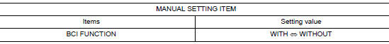
⇔: Items which confirm vehicle specifications
PREDICTIVE COURSE LINE CENTER POSITION ADJUSTMENT
Description
Adjust the center position of the predictive course line of the rear view monitor if it is shifted.
Work Procedure
1.DRIVING
Drive the vehicle straight ahead 100 m (328.1 ft) or more at a speed of 30 km/h (18.6 MPH) or more.
>> END
REAR VIEW CAMERA CALIBRATION
Description
Always perform the calibration after removing and installing or replacing the rear view camera:
- AVM control unit
- Rear view camera
CAUTION:
- Place the vehicle on level ground when the calibration is performed.
- Follow the CONSULT when performing the calibration. (Rear view camera calibration cannot be operated without CONSULT).
Work Procedure (Preparation)
1.PERFORM SELF-DIAGNOSIS
Perform “Self-Diagnosis” of the “AVM” control unit.
Is any DTC detected? Except "U1308">> Perform diagnosis on the detected DTC and repair or replace the applicable item. Refer to DAS-47, "DTC Index".
"U1308" or no DTC>>GO TO 2.
2.PREPARATION BEFORE REAR VIEW CAMERA CALIBRATION
NOTE: Select the "AVM" to diagnose the AVM control unit by CONSULT.
- Perform pre-inspection for diagnosis. Refer to DAS-67, "Inspection Procedure".
- Adjust the tire pressure to the specified pressure value.
- Maintain no-load in vehicle.
- Check if coolant and engine oil are filled up to correct level and fuel tank is full.
- Situate vehicle where the camera is exposed at an atmosphere temperature between 0°C (32°F) and 30°C (86°F)
- Move the shift selector to P (Park) and release the parking brake.
- Clean the rear view camera.
>> GO TO 3.
3.PREPARATION OF CALIBRATION TARGET MARK
Prepare the calibration target mark according to the following figure:
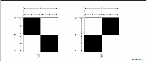
(1) : Left and right targets
(2) : Center target
(A) : Side of the black or white area = 200 mm (7.87 in)
(B) : Side of the square target = 400 mm (15.75 in)
>> Refer to DAS-90, "Work Procedure (Target Setting)".
Work Procedure (Target Setting)
CAUTION:
- Perform this operation in a horizontal position where there is a clear view for 3 m (9.84 ft) backward and 4 m (13.12 ft) wide.
- Place the target in a well-lighted location. (Poor lighting may make it hard to adjust.)
- The target may not be detected when it shines by the reflected light of the sun or lighting.
- The target may not be detected when there is the same pattern of black and white as the target when the pattern is within 0.5 m (1.64 ft) from either side and upward/downward position from the target. (It is desirable that the vehicle is positioned on a single-color floor.)
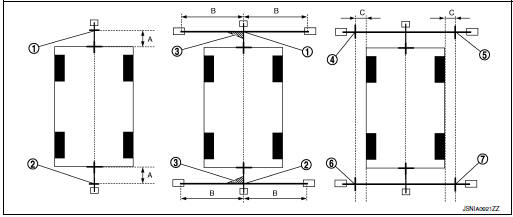
1.TARGET SETTING
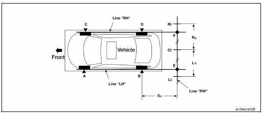
Side distance (Sd): “B”–“E” (“D”–“F”) : 2125 mm (83.66 in)
Left distance (Ld): “Ct”–“Lt” : 1500 mm (59.06 in)
Right distance (Rd): “Ct”–“Rt” : 1500 mm (59.06 in)
- Mark points “A”, “B”, “C” and “D” at the center of the lateral surface
of each wheel.
NOTE: Hang a string with a cone from the fender so as to pass through the center of wheel, and then mark a point at the center of the lateral surface of the wheel.
- Draw line “LH” passing through points “A” and “B” on the left side
of vehicle.
NOTE: Approximately 2.2 m (7.22 ft) or more at the rear from the rear axle.
- Mark point “E” on the line “LH” at the positions 2125 mm (83.66 in) from point “B”.
- Draw line “RH” passing through points “C” and “D” on the right side of vehicle in the same way as step 2.
- Mark point “F” on the line “RH” at the positions 2125 mm (83.66 in) from point “D”.
- Draw line “RW” passing through the points “E” and “F” on the rear
of the vehicle.
NOTE: Approximately 1.8 m (5.91 ft) or more at both left and right sides from vehicle center.
- Mark point “Ct” at the center of point “E” and “F” on the line “RW”.
CAUTION: Make sure that “E” to “Ct” is equal to “F” to “Ct”.
- Mark point "Lt" and "Rt" on the line "RW" at the positions 1500 mm (59.06 in) from point "Ct".
- Position the center of the target mark to point of “Ct”.
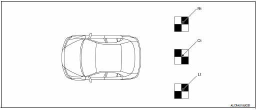
CAUTION: Make sure that the black/white pattern of the center target is rotated as compared with the left and right targets.
>> Go to DAS-91, "Work Procedure (Rear View Camera Calibration)".
Work Procedure (Rear View Camera Calibration)
CAUTION: Perform the calibration under the specified vehicle condition (fuel full, no-load, specified tire pressure, etc.). Refer to DAS-89, "Work Procedure (Preparation)".
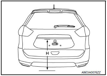
1.CHECK REAR VIEW CAMERA HEIGHT
Measure the rear view camera height “H”.
>> GO TO 2.
2.REAR VIEW CAMERA CALIBRATION
- Select “Work Support” on “AVM” with CONSULT.
- Select “REAR CAMERA ITS”.
- Select "OK".
CAUTION:
- Perform the calibration after the ignition or engine has been kept on for at least 10 minutes to stabilize camera.
- Operate CONSULT outside the vehicle, and close all doors to retain appropriate vehicle altitude.
- Input the rear view camera height "H", and then touch "APPLY".
- Confirm that the same value is displayed on the center display.
- Confirm the following items:
- The target should be accurately placed.
- The vehicle should be stopped.
- The vehicle should be under the specified vehicle condition.
- Select “Start” to perform calibration.
- Confirm the displayed item.
- “Completed”: Select “Completion”.
- Otherwise, perform the following services:
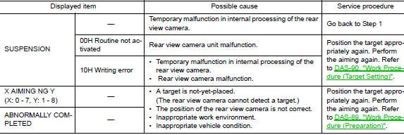
NOTE: Replace camera unit if “00H Routine not activated” or “10H Writing error” are repeatedly indicated during the above two services are performed.
- Confirm that “Completed” is displayed and then select “End” to close the calibration procedure.
>> GO TO 3.
3.PERFORM SELF-DIAGNOSIS
Perform “Self-diagnosis” of “AVM” control unit with CONSULT.
Is any DTC detected? YES >> Perform diagnosis on the detected DTC and repair or replace the applicable item. Refer to DAS- 47, "DTC Index".
NO >> GO TO 4.
4.ACTION TEST
Test the system operation by action test. Refer to DAS-80, "LDW : Description".
>> Work End.
CALIBRATING CAMERA IMAGE (AROUND VIEW MONITOR)
Description
- Calibration must be performed after removing/replacing the cameras, removing parts (e.g. front grille, door mirror, and others) mounted on the cameras, or replacing the Around view monitor control unit.
- The use of CONSULT is required to perform calibration or writing of calibration results to the Around view monitor control unit.
- Align the white lines on the road near the vehicle at the boundary
of each camera image by this camera calibration.
The white lines far from the vehicle may not be aligned at the boundary of each camera image. The farther the line, the greater the difference is.
Work Procedure
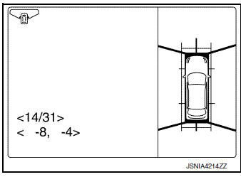
CALIBRATION FLOWCHART
Following the flowchart shown in the figure, perform the calibration.
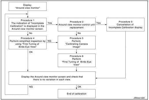
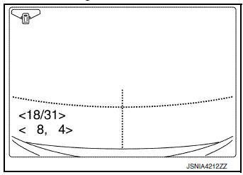
NOTE:
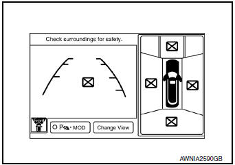
View in the incomplete calibration state is indicated by “ ” on the
around view monitor.
” on the
around view monitor.
CALIBRATION PROCEDURE
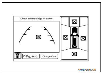
1.AROUND VIEW MONITOR SCREEN CONFIRMATION
Check that there is no indication of “Incomplete calibration”.
Is the “Incomplete calibration” display visible? YES >> GO TO 2.
NO >> GO TO 4.
2.CHECK THAT AROUND VIEW MONITOR CONTROL UNIT IS REPLACED
Check that the around view monitor control unit is replaced.
Is the around view monitor control unit replaced? YES >> GO TO 3.
NO >> GO TO 5.
3.CANCEL THE INDICATION OF INCOMPLETE CALIBRATION (PERFORM THIS ONLY AFTER REPLACING AROUND VIEW MONITOR CONTROL UNIT.)
 CONSULT work support
- On the CONSULT screen, touch “CALIBRATING CAMERA IMAGE (FRONT
CAMERA)”, “CALIBRATING
CAMERA IMAGE (PASS-SIDE CAMERA)”, “CALIBRATING CAMERA IMAGE (DR-SIDE
CAMERA)”, or
“CALIBRATING CAMERA IMAGE (REAR CAMERA)” to accept the selection.
NOTE: To cancel the indication of Incomplete calibration, select items based on the target camera.
- On the adjustment screen of each camera, touch “APPLY” button.
After this, touch “OK” button.
CAUTION:
- Never perform operations other than those mentioned above.
- Never perform “Initialize Camera Image Calibration”.
- Display the around view monitor screen to check that there is no errors, such as deviations among the camera images.
Is there a malfunction? YES >> Calibration End.
NO >> GO TO 1.
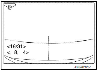
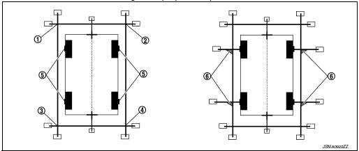
4.PERFORM SIMPLIFIED CONFIRMATION/ADJUSTMENT BY “FINE TUNING OF BIRDS-EYE VIEW”
- Put target line 1 on the ground beside each axle using packing tape, etc.
- Put target lines 2 equal to the vehicle total length + approximately 1.0 m (39.3 in) from the vehicle side (right and left) at approximately 30 cm (11.8 in) away from the vehicle (make the line as parallel with the vehicle as possible)
Preparation of simplified target line
- Target lines 1
- Target lines 2
- Approx. 30 cm (11.8 in)
- Approx. 1.0 m (39.3 in)
 CONSULT work support
Touch “FINE TUNING OF BIRDS-EYE VIEW” on the CONSULT screen.
CONSULT work support
Touch “FINE TUNING OF BIRDS-EYE VIEW” on the CONSULT screen.- On the CONSULT screen, touch “SELECT” button to select right or left camera and perform camera calibration as instructed below:
- If the marker on the screen deviates from Target line 1, touch “AXIS X” button and “AXIS Y” button to adjust so that the marker is placed on the Target line 1.
- If Target line 2 is misaligned among the cameras, adjust each
camera image to bring Target line 2 into a
straight line.
CAUTION: Never adjust the front camera and rear camera. Only adjust the right and left cameras.
Simplified target line adjustment method
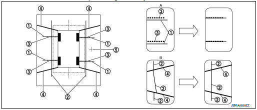
- Target lines 1
- Target lines 2
- Marker for target line 1
- Boundary between cameras
- Crosshairs cursor (mark indicated the selected camera)
- Adjustment method for target lines 1 (right)
- Adjustment method for target lines 2 (right)
- Adjust right and left cameras. Touch "APPLY" on the CONSULT screen to display adjustment results.
- After adjusting right and left cameras, check that the marker is properly placed on the screen and there is no deviation in Target line 1.
NOTE:
- It can be initialized to the NISSAN factory default condition with “Initialize Camera Image Calibration”.
- The adjustment value is cancelled on this mode by performing “Initialize Camera Image Calibration”.
Is the difference corrected? YES >> On the CONSULT screen, touch “OK” button to complete writing to the around view monitor control unit.
NO >> GO TO 5.
5.PERFORM “CALIBRATING CAMERA IMAGE”
Preparation of target line
- Hang a string with a weight as shown in the figure. Put the points FM0, RM0 (mark) on the ground at the center of the vehicle front end and rear end with white packing tape or a pen.
- Route the vinyl string under the vehicle, and then pull and fix it on the point approximately 1.0 m (39.9 in) to the front and rear of the vehicle through the points FM0 and RM0 using packing tape.
Target line preparation procedure 1
- Thread
- Weight
- Point FM0 (mark)
- Point RM0 (mark)
- Packing tape (to fix the vinyl string)
- Vinyl string
- Put the points FM and RM (mark) 75 cm (29.5 in) from the points FM0 and RM0 individually.
- Route the vinyl string through the points FM and RM using a triangle scale, and then fix it at approximately 1.5 m (59 in) on both sides with packing tape.
- Put the points FL, FR, RL, and RR (mark) to both right and left [vehicle width / 2 + 30 cm (11.8 in)] from the points FM and RM.
Target line preparation procedure 2
- Point FM
- Point RM
- Triangle scale
- Point FL (mark)
- Point FR (mark)
- Point RL (mark)
- Point RR (mark)
- 75 cm (29.5 in)
- Approx. 1.5 m (59 in)
- 30 cm (11.8 in) [Vehicle width/ 2 + 30 cm (11.8 in) from the points FM and RM]
- Draw the lines of the points FL – RL and FR – RR with vinyl string, and fix it with packing tape.
- Put a mark on the center of each axle, draw vertical lines to the lines of the points FL – RL and FR – RR from the marks on the center of the axle using a triangle scale, and then fix the lines using packing tape.
Target line preparation procedure 3
- Point FL
- Point FR
- Point RL
- Point RR
- Center position of axle
- Triangle scale
Perform “Calibrating Camera Image”
 CONSULT work support
- . On the CONSULT screen, touch “CALIBRATING CAMERA IMAGE (FRONT
CAMERA)”, “CALIBRATING
CAMERA IMAGE (PASS-SIDE CAMERA)”, “CALIBRATING CAMERA IMAGE (DR-SIDE
CAMERA)”, or
“CALIBRATING CAMERA IMAGE (REAR CAMERA)” to accept the selection.
NOTE: To cancel the indication of Incomplete calibration, select items based on the target camera.
- On the adjustment screen of each camera, adjust the parameter by touching the “AXIS X” button, “AXIS Y” button, and “ROTATE” button to place the calibration marker shown on the camera screen on the target line drawn on the ground.
Adjustment range
Rotation direction (Center dial) : 31 patterns (16 on the center)
Upper/lower direction (upper/lower
switch) : −22 – 22
Left/right direction (left/right switch) : −22 – 22
- Touch “APPLY” button on the CONSULT screen. “PRCSNG” is
displayed and adjustment results are shown on the camera screen.
CAUTION: Check that “PRCSNG” is displayed. Never perform other operations while “PRCSNG” is displayed.
- Touch “OK” button on the CONSULT screen. “PRCSNG” is displayed and
adjustment results are written to
the around view monitor control unit.
CAUTION: Check that “PRCSNG” is displayed. Never perform other operations while “PRCSNG” is displayed.
>> GO TO 6.
6.PERFORM “FINE TUNING OF BIRDS-EYE VIEW”
This mode is designed to align the boundary between each camera image that could not be aligned in the
“Calibrating Camera Image” mode.
CONSULT work support
- Select “FINE TUNING OF BIRDS-EYE VIEW” by touching CONSULT screen.
- On the adjustment screen of each camera, adjust the parameter
by touching the “AXIS X” button, “AXIS Y” button”, and
“ROTATE” button to place the calibration marker shown on the
camera screen on the target line drawn on the ground.
NOTE: Touch “SELECT” button on the CONSULT screen to select the target camera.
- Touch “APPLY” button on the CONSULT screen. “PRCSNG” is
displayed and adjustment results are shown on the camera
screen.
CAUTION: Check that “PRCSNG” is displayed. Never perform other operations while “PRCSNG” is displayed.
- Touch “OK” button on the CONSULT screen. “PRCSNG” is displayed and adjustment results are written to the around view monitor control unit.
CAUTION:
- Check that “PRCSNG” is displayed. Never perform other operations while “PRCSNG” is displayed.
- After pressing the “OK” button, never press buttons other than the “BACK” button.
NOTE:
- It can be initialized to the NISSAN factory default condition with “Initialize Camera Image Calibration”.
- The adjustment value is cancelled in this mode by performing “Initialize Camera Image Calibration”.
>> Calibration End.
 Wiring diagram
DRIVER ASSISTANCE SYSTEMS
Wiring Diagram
...
 DTC/circuit diagnosis
U0121 VDC CAN 2
DTC Logic
DTC DETECTION LOGIC
NOTE:
If DTC U0121 is displayed with DTC U1000, first perform the trouble diagnosis
for DTC U1000. Refer to DAS-
106, "DISTANCE SENSOR : DTC L ...
Other materials:
Adjust
For adjustable head restraint/headrest
Adjust the head restraint/headrest so the center
is level with the center of your ears. If your ear
position is still higher than the recommended
alignment, place the head restraint/headrest at
the highest position.
For non-adjustable head restraint ...
Brake master cylinder
Exploded View
Reservoir cap
Oil strainer
Reservoir tank
Brake fluid level sensor
Cylinder body
Pin
O-ring
Grommet
: Apply PBC (Poly Butyl
Cuprysil) grease or silicone-based grease.
: Apply brake fluid.
Removal and Installation
REMOVAL
CAUTION:
Do ...
Power supply and ground circuit
Diagnosis Procedure
1.CHECK FUSE
Check that the following fuse is not fusing.
Is the fuse fusing?
YES >> Replace the fuse after repairing the applicable circuit.
NO >> GO TO 2.
2.CHECK GROUND CONNECTION
Turn ignition switch OFF.
Check ground connection E9 or E ...
