Nissan Rogue Service Manual: Power supply and ground circuit
Diagnosis Procedure
1.CHECK FUSE
Check that the following fuse is not fusing.
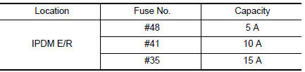
Is the fuse fusing? YES >> Replace the fuse after repairing the applicable circuit.
NO >> GO TO 2.
2.CHECK GROUND CONNECTION
- Turn ignition switch OFF.
- Check ground connection E9 or E15. Refer to GI-44, "Circuit Inspection".
Is the inspection result normal? YES >> GO TO 3.
NO >> Repair or replace ground connection.
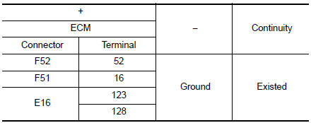
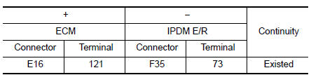
3.CHECK ECM GROUND CIRCUIT
- Disconnect ECM harness connectors.
- Check the continuity between ECM harness connector and ground.
Is the inspection result normal? YES >> GO TO 4.
NO >> Repair or replace error-detected parts.
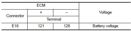
4.CHECK ECM POWER SUPPLY (MAIN)-1
- Reconnect ECM harness connector.
- Turn ignition switch ON.
- Check the voltage between ECM harness connector terminals.
Is the inspection result normal? YES >> GO TO 5.
NO >> GO TO 6.
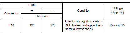
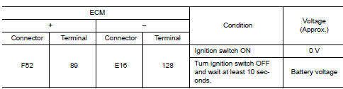
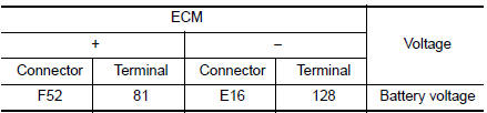
5.CHECK ECM POWER SUPPLY (MAIN)--2
- Turn ignition switch OFF and wait at least 10 seconds.
- Check the voltage between ECM harness connector terminals as per the following.
Is the inspection result normal? YES >> GO TO 9.
NO >> GO TO 7.
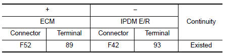
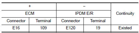
6.CHECK ECM POWER SUPPLY (MAIN) CIRCUIT
- Turn ignition switch OFF.
- Disconnect ECM harness connectors.
- Disconnect IPDM E/R harness connector.
- Check the continuity between ECM harness connector and IPDM E/R harness connector.
- Also check harness for short to ground.
Is the inspection result normal? YES >> Perform the trouble diagnosis for power supply circuit.
NO >> Repair or replace error-detected parts.
7.CHECK ECM RELAY CONTROL SIGNAL
Check the voltage between ECM harness connector terminals as per the following.
Is the inspection result normal? YES >> Check Intermittent Incident. Refer to GI-41, "Intermittent Incident".
NO >> GO TO 8.
8.CHECK ECM RELAY CONTROL SIGNAL CIRCUIT
- Turn ignition switch OFF.
- Disconnect ECM harness connector.
- Disconnect IPDM E/R harness connector
- Check the continuity between ECM harness connector and IPDM E/R harness connector.
- Also check harness for short to ground and to power.
Is the inspection result normal? YES >> Replace IPDM E/R. Refer to PCS-35, "Removal and Installation".
NO >> Repair or replace error-detected parts.
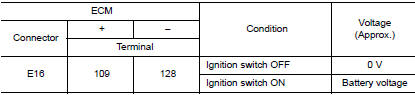
9.CHECK IGNITION SWITCH SIGNAL
- Turn ignition switch ON.
- Check the voltage between ECM harness connector terminals.
Is the inspection result normal? YES >> GO TO 11.
NO >> GO TO 10.
10.CHECK IGNITION SWITCH SIGNAL CIRCUIT
- Turn ignition switch OFF.
- Disconnect ECM harness connector.
- Disconnect IPDM E/R harness connector.
- Check the continuity between ECM harness connector and IPDM E/R harness connector.
- Also check harness for short to ground and to power.
Is the inspection result normal? YES >> Perform the trouble diagnosis for power supply circuit.
NO >> Repair or replace error-detected parts.
11.CHECK ECM POWER SUPPLY (BACK-UP)
Check the voltage between ECM harness connector terminals.
Is the inspection result normal? YES >> Check Intermittent Incident. Refer to GI-41, "Intermittent Incident".
NO >> GO TO 12.
12.CHECK ECM POWER SUPPLY (BACK-UP) CIRCUIT
- Turn ignition switch OFF.
- Disconnect ECM harness connector.
- Disconnect IPDM E/R harness connector.
- Check the continuity between ECM harness connector and IPDM E/R harness connector.
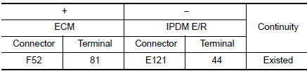
- Also check harness for short to ground and to power.
Is the inspection result normal? YES >> Perform the trouble diagnosis for power supply circuit.
NO >> Repair or replace error-detected parts.
 Trouble diagnosis - specification value
Description
The specification (SP) value indicates the tolerance of the value that is
displayed in ŌĆ£SPECŌĆØ of ŌĆ£DATA MONITORŌĆØ
mode of CONSULT during normal operation of the Engine Control Sy ...
 U0101 CAN comm circuit
Description
CAN (Controller Area Network) is a serial communication line for real time
application. It is an on-vehicle multiplex
communication line with high data communication speed and excellen ...
Other materials:
Mirrors
Rearview mirror (if so equipped)
Rearview mirror (if so equipped)
Use the night position 1 to reduce glare from
the headlights of vehicles behind you at night.
Use the day position 2 when driving in daylight
hours.
WARNINGUse the night position only when necessary,
because it r ...
Removal and installation
GENERATOR
Exploded View
REMOVAL
Cylinder head
Generator bracket
Washer
Generator
Water pump
Cylinder block
Removal and Installation
REMOVAL
Disconnect negative terminal from battery. Refer to PG-75,
"Exploded View".
Remove wheel and tire ...
Precaution
Precaution for Supplemental Restraint System (SRS) "AIR BAG" and "SEAT
BELT
PRE-TENSIONER"
The Supplemental Restraint System such as ŌĆ£AIR BAGŌĆØ and ŌĆ£SEAT BELT PRE-TENSIONERŌĆØ,
used along
with a front seat belt, helps to reduce the risk or severity of injury to the
...
