Nissan Rogue (T33) 2021-Present Service Manual: B2fae-14 Ignition Relay-1
DTC Description
DTC DETECTION LOGIC
| DTC No. |
CONSULT screen items (Trouble diagnosis content) | DTC detection condition | |
|---|---|---|---|
| B2FAE-14 |
Ignition relay-1 (Ignition relay-1) |
Diagnosis condition | When ignition switch is OFF |
| Signal (terminal) | Ignition relay-1 control signal [terminal #122 (with type A meter) or terminal #105 (with type B meter)] | ||
| Threshold | 0 V | ||
| Diagnosis delay time | 1 second or more | ||
POSSIBLE CAUSE
-
Harness or connectors (ignition relay-1 control signal circuit is open or shorted to ground)
-
Ignition relay-1
-
BCM
FAIL-SAFE
Inhibit engine cranking
DTC CONFIRMATION PROCEDURE
PERFORM DTC CONFIRMATION PROCEDURE
 CONSULT
-
Ignition switch ON.
-
Ignition switch OFF and wait for 1 second or more.
-
Ignition switch ON.
-
Select “Self diagnosis result” mode of “BCM”.
Is DTC detected?
YES>>Refer to DTC Diagnosis Procedure.
NO-1>>To check malfunction symptom before repair: Refer to Intermittent Incident.
NO-2>>Confirmation after repair: Inspection End.
DTC Diagnosis Procedure
CHECK IGNITION RELAY-1 CONTROL SIGNAL VOLTAGE
-
Ignition switch OFF.
-
Disconnect BCM connector.
-
Check voltage between BCM harness connector and ground.
With type A meter + - Voltage
(Approx.)BCM Connector Terminal E60 122 Ground Battery voltage With type B meter + - Voltage
(Approx.)BCM Connector Terminal E29 105 Ground Battery voltage
Is the inspection result normal?
YES>>Replace BCM. Refer to Removal and Installation.
NO>>GO TO 2.
CHECK IGNITION RELAY-1 CONTROL SIGNAL CIRCUIT (OPEN)
-
Disconnect ignition relay-1 connector.
-
Check continuity between BCM harness connector and ignition relay-1 connector.
With type A meter BCM Ignition relay-1 Continuity Connector Terminal Connector Terminal E60 122 J-3 1 Yes With type B meter BCM Ignition relay-1 Continuity Connector Terminal Connector Terminal E29 105 J-3 1 Yes
Is the inspection result normal?
YES>>GO TO 3.
NO>>Repair the harness or connector.
CHECK IGNITION RELAY-1 CONTROL SIGNAL CIRCUIT (SHORT TO GROUND)
Check continuity between BCM harness connector and ground.
| BCM | — | Continuity | |
|---|---|---|---|
| Connector | Terminal | ||
| E60 | 122 | Ground | No |
| BCM | — | Continuity | |
|---|---|---|---|
| Connector | Terminal | ||
| E29 | 105 | Ground | No |
Is the inspection result normal?
YES>>GO TO 4.
NO>>Repair the harness or connector.
CHECK IGNITION RELAY-1
Check ignition relay-1. Refer to Component Inspection.
Is the inspection result normal?
YES>>Inspection End.
NO>>Replace ignition relay-1.
Component Inspection
CHECK IGNITION RELAY-1
-
Ignition switch OFF.
-
Disconnect ignition relay-1 connector.
-
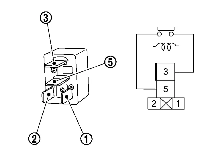
Check continuity between ignition relay-1 terminals.
| Ignition relay-1 | Condition | Continuity | |
|---|---|---|---|
| Terminal | |||
 |
 |
12 V direct current supply between terminals  and and  . . |
Yes |
| No current supply | No | ||
Is the inspection result normal?
YES>>Inspection End.
NO>>Replace ignition relay-1.
Other materials:
U2b8c-88 Ethernet Circuit
DTC Description
DTC DETECTION LOGIC DTC No. CONSULT screen terms DTC detected condition
U2B8C-88
Ethernet circuit
Diagnosis condition
When ignition switch is ON.
Signal (terminal)
—
Threshold
Lost ethernet communication with driving video recorder control module
...
Front Wheel Hub and Knuckle
Exploded View
Steering knuckle
Splash guard
Hub bolt
Wheel hub and bearing assembly
Disc rotor
Wheel hub lock nut
: Comply with the installation procedure when tightening. Refer to Removal and Installation.
: N·m (kg-m, ft-lb)
: Always replace aft ...
C1213-A3 Control Unit Power Supply
DTC Description
DTC DETECTION LOGIC DTC
CONSULT screen terms
(Trouble diagnosis content) DTC detecting condition
C1213-A3
BATTERY VOLTAGE
(Battery voltage)
Diagnosis condition
Ignition switch: ON
Signal
Battery power supply signal (terminal #6)
Threshold
Battery po ...