Nissan Rogue Service Manual: Wiring diagram
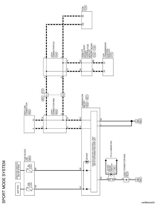
SPORT MODE SYSTEM
Wiring Diagram

 ECU diagnosis information
SPORT MODE
List of ECU Reference
...
 Basic inspection
DIAGNOSIS AND REPAIR WORK FLOW
Work Flow
DETAILED FLOW
1.OBTAIN INFORMATION ABOUT SYMPTOM
Interview the customer to obtain as much information as possible about the
conditions and environment un ...
Other materials:
Rear window defogger switch
WITH MANUAL A/C
WITH MANUAL A/C : Description
The rear window defogger is operated by pressing the rear window
defogger switch ON.
The indicator lamp in the rear window defogger switch illuminates
while the rear window defogger is ON.
WITH MANUAL A/C : Component Function Check
...
Door mirror
Exploded View
Door mirror
Door mirror corner finisher
Door mirror rear finisher
Side turn signal lamp
Side camera (if equipped)
Door mirror glass
Pawl
Removal and Installation
REMOVAL
Remove front door finisher. Refer to INT-15, "Removal and
...
Warning/indicator lights
Warning
light
Name
Anti-lock Braking
System (ABS) warning
light
Brake warning light
Charge warning
light
Low tire pressure
warning light
Low windshield
washer fluid warning
light
Master w ...
