Nissan Rogue Service Manual: The liftgate open warning continues displaying, or does not display
Description
- The liftgate open warning is displayed continuously even though the liftgate is closed.
- The liftgate open warning is not displayed even though the liftgate is open.
Diagnosis Procedure
1.CHECK BCM INPUT SIGNAL
Check the BCM input signal. Refer to DLK-149, "Component Function Check" (with Intelligent Key system) or DLK-319, "Component Function Check" (without Intelligent Key system).
Is the inspection result normal? YES >> GO TO 2.
NO >> GO TO 3.
2.CHECK COMBINATION METER INPUT SIGNAL
Select the "METER/M&A" "Data Monitor" and check the "DOOR W/L" monitor value while opening and closing the back door.
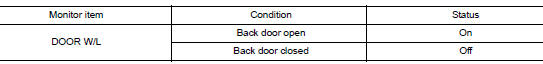
Is the inspection result normal? YES >> Replace combination meter. Refer to MWI-82, "Removal and Installation".
NO >> Replace BCM. Refer to BCS-75, "Removal and Installation" (with Intelligent Key system) or BCS- 135, "Removal and Installation" (without Intelligent Key system).
3.CHECK BACK DOOR SWITCH SIGNAL CIRCUIT
Check the back door switch signal circuit. Refer to DLK-151, "Diagnosis Procedure (With Automatic Back Door)" or DLK-152, "Diagnosis Procedure (Without Automatic Back Door)".
Is the inspection result normal? YES >> GO TO 4.
NO >> Repair or replace harness or connector.
4.CHECK BACK DOOR SWITCH
Check the back door switch. Refer to DLK-153, "Component Inspection (With Automatic Back Door)" or DLK- 154, "Component Inspection (Without Automatic Back Door)".
Is the inspection result normal? YES >> Replace combination meter. Refer to MWI-82, "Removal and Installation".
NO >> Replace back door switch. Refer to DLK-263, "DOOR LOCK : Removal and Installation".
 The door open warning continues displaying, or does not
display
The door open warning continues displaying, or does not
display
Description
The door open warning is displayed even though all of the doors are
closed.
The door open warning is not displayed even though a door is ajar.
Diagnosis Procedure
1.CHEC ...
 The meter control switch is inoperative
Description
The meter control switches are inoperative when pressed.
Diagnosis Procedure
1.CHECK METER CONTROL SWITCH SIGNAL
Check the meter control switch signal. Refer to MWI-67, "Diagnosis ...
Other materials:
U1000 CAN COMM circuit
DTC Logic
DTC DETECTION LOGIC
DTC
CONSULT
Detection Condition
Possible Cause
U1000
CAN COMM CIRC
[U1000]
When combination meter is not transmitting or receiving CAN
communication signals for 2 seconds or more.
CAN communication system
D ...
Unit removal and installation
TRANSAXLE ASSEMBLY
Exploded View
Transaxle assembly
O-ring
CVT fluid charging pipe
CVT fluid charging pipe cap
For the tightening torque, refer to TM-220, "Removal and
Installation".
Always replace after every
disassembly.
: N·m (kg-m, ft-lb)
: N·m ...
P0102, P0103 MAF sensor
DTC Description
DTC DETECTION LOGIC
DTC No.
CONSULT screen terms
(Trouble diagnosis content)
DTC detecting condition
P0102
MAF SEN/CIRCUIT-B1
(Mass or volume air flow ″A″ circuit low)
An excessively low voltage from the mass air flow sensor is sent to ...
