Nissan Rogue Service Manual: System description
DESCRIPTION
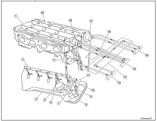
Engine Lubrication System

- Camshaft (INT)
- Chain tensioner
- Main gallery
- Oil pan
- Oil cooler
- Balancer unit
- Oil pan oil gallery
- Oil filter (with relief valve)
- Oil Strainer
- Oil pump
- Timing chain and balancer unit timing chain oil jet
- Intake valve timing intermediate lockcontrol solenoid valve
- Intake valve timing control cover
- Intake valve timing control solenoid valve
- Exhaust valve timing control solenoid valve
- Front cover
- Exhaust valve timing controller
- Intake valve timing controller
- Camshaft (EXH)
Engine Lubrication System Schematic

- Oil pan
- Oil strainer
- Oil pump
- Regulator valve
- Oil filter
- Relief valve (Built in oil filter)
- Oil cooler
- Relief valve
- Chain oil jet
- Main gallery
- Piston oil jet
- Cylinder head
- C-VTC oil filter
- C-VTC EXH solenoid valve
- C-VTC intermediate solenoid valve
- C-VTC INT solenoid valve
- C-VTC exhaust
- C-VTC intermediate
- C-VTC intake
- Camshaft journal
- Camshaft
- Chain tensioner
- Balancer housing
- Balancershaft journal
- Main bearing
- Crankshaft
- Connectiong rod bearing
- Connectiong rod
- Piston
 Preparation
Special Service Tools
The actual shape of the tools may differ from those illustrated here.
Tool number
(TechMate No.)
Tool name
Description
KV10111100
(J-37228)
...
Other materials:
Basic inspection
DIAGNOSIS AND REPAIR WORK FLOW
Work Flow
OVERALL SEQUENCE
DETAILED FLOW
1.GET INFORMATION FOR SYMPTOM
Get detailed information from the customer about the symptom (the
condition and the environment when
the incident/malfunction occurs).
Check operation condition of the ...
Precaution
Precaution for Supplemental Restraint System (SRS) "AIR BAG" and "SEAT
BELT
PRE-TENSIONER"
The Supplemental Restraint System such as “AIR BAG” and “SEAT BELT PRE-TENSIONER”,
used along
with a front seat belt, helps to reduce the risk or severity of injury to the
...
P0128 thermostat function
DTC Description
DTC DETECTION LOGIC
Engine coolant temperature has not risen enough to open the thermostat even
though the engine has run long
enough.
This is due to a leak in the seal or the thermostat being stuck open.
DTC No.
CONSULT screen terms
(Trouble diagnosis content)
...

