Nissan Rogue Service Manual: System
System Description
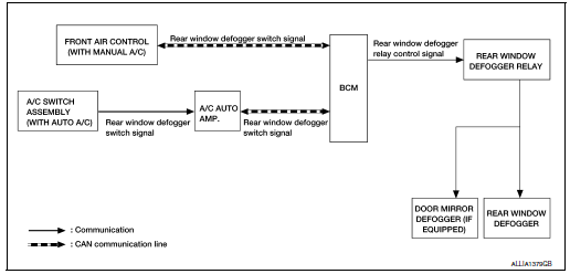
SYSTEM DIAGRAM
OPERATION DESCRIPTION
- When rear window defogger switch is turned ON while ignition switch is ON, the rear window defogger switch transmits rear window defogger switch signal to BCM.
- BCM turns rear window defogger relay ON when rear window defogger switch signal is received.
- Rear window defogger and door mirror defogger (with door mirror defogger) are supplied with power and operate when rear window defogger relay turns ON.
- Rear window defogger ON is displayed when front air control (manual A/C) or A/C switch (auto A/C) receives signals.
TIMER FUNCTION
- BCM turns rear window defogger relay ON for approximately 15 minutes when rear window defogger switch is turned ON while ignition switch is ON. It makes rear window defogger and door mirror defogger (with door mirror defogger) operate.
- Timer is canceled after pressing rear window defogger switch again during timer operation. Then BCM turns rear window defogger relay OFF. The same reaction also occurs during timer operation, if the ignition switch is turned OFF.
INPUT/OUTPUT SIGNAL CHART
|
Switch |
Input signal to BCM |
BCM function |
Actuato |
| Rear window defogger switch | Defogger switch signal | Rear window defogger and door mirror defogger* control | Rear window defogger Door mirror defogger * |
*: With door mirror defogger
 Component parts
Component Parts Location
A/C switch (auto A/C)
Front air control (manual A/C)
No.
Component
Description
1
Rear window defogger connector
(Rear win ...
 Diagnosis system (BCM) (with intelligent key system)
COMMON ITEM
COMMON ITEM : CONSULT Function (BCM - COMMON ITEM)
APPLICATION ITEM
CONSULT performs the following functions via CAN communication with BCM.
Direct Diagnostic Mode
De ...
Other materials:
Anti-lock Braking System (ABS)
WARNING
The Anti-lock Braking System (ABS) is a
sophisticated device, but it cannot prevent
accidents resulting from careless
or dangerous driving techniques. It can
help maintain vehicle control during
braking on slippery surfaces. Remember
that stopping dis ...
Maintenance precautions
When performing any inspection or maintenance
work on your vehicle, always take care to prevent
serious accidental injury to yourself or damage to
the vehicle. The following are general precautions
which should be closely observed.
WARNING
Park the vehicle on a level surface, a ...
Basic inspection
DIAGNOSIS AND REPAIR WORK FLOW
Work flow
OVERALL SEQUENCE
DETAILED FLOW
1.OBTAIN INFORMATION ABOUT SYMPTOM
Interview the customer to obtain as much information as possible about the
conditions and environment under
which the malfunction occurred.
>> GO TO 2.
2.CHECK SYMPTOM
...
