Nissan Rogue Service Manual: Sample/Wiring Diagram -Example-
Each section includes wiring diagrams.
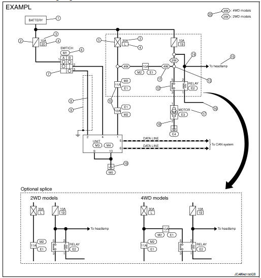
Description
| Number | Item | Description |
| 1 | Power supply |
|
| 2 | Fuse |
|
| 3 | Current rating of fusible link/fuse |
|
| 4 | Number of fusible link/ fuse |
|
| 5 | Fusible link |
|
| 6 | Connector number |
|
| 7 | Switch |
|
| 8 | Circuit (Wiring) |
|
| 9 | Shielded line |
|
| 10 | Connectors |
|
| 11 | Option abbreviation |
|
| 12 | Relay |
|
| 13 | Optional splice |
|
| 14 | Splice |
|
| 15 | System branch |
|
| 16 | Page crossing |
|
| 17 | Component name |
|
| 18 | Terminal number |
|
| 19 | Ground (GND) |
|
| 20 | Explanation of option description |
|
 ”.
”. ” means the splice.
SWITCH POSITIONS
Switches are shown in wiring diagrams as if the vehicle is in the “normal” condition.
A vehicle is in the “normal” condition when:
- ignition switch is “OFF”
- doors, hood and trunk lid/back door are closed
- pedals are not depressed
- parking brake is released
MULTIPLE SWITCH
The continuity of multiple switch is described in two ways as shown below.
- The switch chart is used in schematic diagrams.
- The switch diagram is used in wiring diagrams.
 Connector Symbols
Most of connector symbols in wiring diagrams are shown from the terminal
side.
Connector symbols shown from the terminal side are enclosed by
a single line and followed by the direction ...
 Connector Information
HOW TO USE CONNECTOR INFORMATION
Description
Number
Item
Description
1
Connector number
Alphabetic characters show to which harness the connector is
pla ...
Other materials:
Unit disassembly and assembly
ELECTRIC CONTROLLED COUPLING
Exploded View
Stud bolt
Connector bracket
Reamer bolt
Electric controlled coupling assembly
Wave spring
Drive pinion oil seal
Drive pinion lock nut
Pinion front bearing
Gear carrier
Collapsible spacer
Drive pinion adjusting shim
Pini ...
CVT control system
Wiring Diagram
...
Vehicle Dynamic Control (VDC) system
The Vehicle Dynamic Control (VDC) system uses
various sensors to monitor driver inputs and vehicle
motion. Under certain driving conditions,
the VDC System helps to perform the following
functions:
Controls brake pressure to reduce wheel
slip on 1 slipping drive wheel so power is
t ...
