Nissan Rogue Service Manual: How to use this manual
How to use this manual
Description
This volume explains “Removal, Disassembly, Installation, Inspection and Adjustment” and “Trouble Diagnoses”.
Terms
- The captions WARNING and CAUTION warn you of steps that must be followed
to prevent personal injury
and/or damage to some part of the vehicle.
WARNING indicates the possibility of personal injury if instructions are not followed.
CAUTION indicates the possibility of component damage if instructions are not followed.
BOLD TYPED STATEMENTS except WARNING and CAUTION give you helpful information.
Standard value: Tolerance at inspection and adjustment.
Limit value: The maximum or minimum limit value that should not be exceeded at inspection and adjustment.
Units
The UNITS given in this manual are primarily expressed as the SI UNIT (International System of Unit), and alternatively expressed in the metric system and in the yard/pound system.
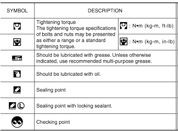
Also with regard to tightening torque of bolts and nuts, there are descriptions both about range and about the standard tightening torque.
“Example”
Range
Outer Socket Lock Nut : 59 - 78 N·m (6.0 - 8.0 kg-m, 43 - 58 ft-lb)
Standard
Drive Shaft Installation Bolt : 44.3 N·m (4.5 kg-m, 33 ft-lb)
Contents
- QUICK REFERENCE INDEX, a black tab (e.g.
 ) is provided on the first page.
You can quickly find the
first page of each section by matching it to the section's black tab.
 - THE CONTENTS are listed on the first page of each section.
- THE TITLE is indicated on the upper portion of each page and shows the part or system.
- THE PAGE NUMBER of each section consists of two or three letters which designate the particular section and a number (e.g. “BR-5”).
- THE SMALL ILLUSTRATIONS show the important steps such as
inspection, use of special tools, knacks of
work and hidden or tricky steps which are not shown in the previous large
illustrations.
Assembly, inspection and adjustment procedures for the complicated units such as the automatic transaxle or transmission, etc. are presented in a step-by-step format where necessary.
Relation between illustrations and descriptions
The following sample explains the relationship between the part description in an illustration, the part name in the text and the service procedures.

Components
- THE LARGE ILLUSTRATIONS are exploded views (see the following) and
contain tightening torques, lubrication
points, section number of the PARTS CATALOG (e.g. SEC. 440) and other
information necessary to
perform repairs.
The illustrations should be used in reference to service matters only. When ordering parts, refer to the appropriate PARTS CATALOG.
Components shown in an illustration may be identified by a circled number. When this style of illustration is used, the text description of the components will follow the illustration.

- Cap
- Bleeder valve
- Cylinder body
- Piston seal
- Piston
- Piston boot
- Sliding pin
- Sliding pin boot
- Bushing
- Torque member
 Apply rubber grease.
 Apply brake fluid.
 N·m (kg-m, in-lb)
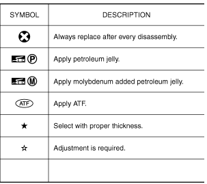
 Always replace after every
disassembly
SYMBOLS


- How to follow trouble diagnoses
- How to read wiring diagrams
- Abbreviations
- Tightening torque of standard bolts
- Recommended chemical products and sealants
 How to follow trouble diagnoses
Description
NOTICE:
Trouble diagnoses indicate work procedures required to diagnose problems
effectively. Observe the following
instructions before diagnosing.
Before performing trouble ...
Other materials:
Front power seat adjustment (if so equipped)
Operating tips
The power seat motor has an auto-reset
overload protection circuit. If the motor
stops during operation, wait 30 seconds
then reactivate the switch.
Do not operate the power seat switch for a
long period of time when the engine is off.
This will dischar ...
Charging system preliminary inspection
Diagnosis Procedure
1.CHECK BATTERY TERMINALS CONNECTION
Check if battery terminals are clean and tight.
Is the inspection result normal?
YES >> GO TO 2.
NO >> Repair battery terminal connection. Confirm repair by performing complete
Charging system test
using EXP-800 NI or G ...
C119A vacuum sensor
DTC Logic
DTC DETECTION LOGIC
DTC
Display Item
Malfunction detected condition
Possible causes
C119A
VACUUM SEN VOLT
When a malfunction is detected in supply power voltage
of vacuum sensor.
Harness or connector
Vacuum sensor (brake booster)
...

