Nissan Rogue Service Manual: C119A vacuum sensor
DTC Logic
DTC DETECTION LOGIC
| DTC | Display Item | Malfunction detected condition | Possible causes |
| C119A | VACUUM SEN VOLT | When a malfunction is detected in supply power voltage of vacuum sensor. |
|
DTC CONFIRMATION PROCEDURE
1.CHECK SELF-DIAGNOSTIC RESULT
 With CONSULT.
- Turn the ignition switch ON.
- Perform self-diagnostic result.
Is DTC C119A detected? YES >> Proceed to diagnosis procedure. Refer to BRC-111, "Diagnosis Procedure".
NO >> Inspection End.
Diagnosis Procedure
Regarding Wiring Diagram information, refer to BRC-57, "Wiring Diagram".
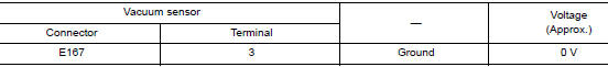
1.CHECK VACUUM SENSOR POWER SUPPLY
- Turn the ignition switch OFF.
- Disconnect vacuum sensor harness connector.
- Check voltage between vacuum sensor harness connector and ground.
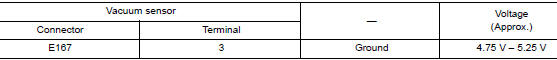
- Turn the ignition switch ON.
CAUTION: Never start engine.
- Check voltage between vacuum sensor harness connector and ground.
Is the inspection result normal? YES >> GO TO 3.
NO >> GO TO 2.
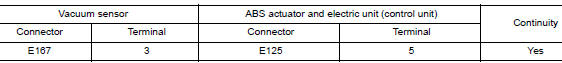
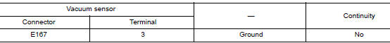
2.CHECK VACUUM SENSOR POWER SUPPLY CIRCUIT
- Turn the ignition switch OFF.
- Disconnect ABS actuator and electric unit (control unit) harness connector.
- Check continuity between vacuum sensor harness connector and ABS actuator and electric unit (control unit) harness connector.
- Check continuity between vacuum sensor harness connector and ground.
Is the inspection result normal? YES >> Perform diagnosis of ABS actuator and electric unit (control unit) power supply and ground circuit.
Refer to BRC-111, "Diagnosis Procedure".
NO >> Repair or replace malfunctioning components.
3.CHECK VACUUM SENSOR GROUND CIRCUIT
- Turn the ignition switch OFF.
- Check continuity between vacuum sensor harness connector and ground.
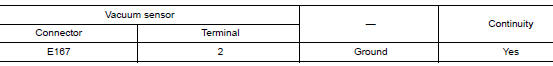
Is the inspection result normal? YES >> GO TO 4.
NO >> Repair or replace malfunctioning components.
4.CHECK TERMINAL
- Check vacuum sensor pin terminals for damage or loose connection with harness connector.
- Check ABS actuator and electric unit (control unit) pin terminals for damage or loose connection with harness connector.
Is the inspection result normal? YES >> Replace ABS actuator and electric unit (control unit). Refer to BRC-136, "Removal and Installation".
NO >> Repair or replace malfunctioning components.
 C1199 brake booster
DTC Logic
DTC DETECTION LOGIC
DTC
Display Item
Malfunction detected condition
Possible causes
C1199
BRAKE BOOSTER
When brake booster vacuum is approx. 0 kPa (0 mm-
...
 U1000 CAN COMM CIRCUIT
Description
CAN communication allows a high rate of information transmission through the
two communication lines
(CAN-H line and CAN-L line) connecting various control units in the system. Each
...
Other materials:
P0779 pressure control solenoid B
DTC Description
DTC DETECTION LOGIC
DTC
CONSULT screen terms
(Trouble diagnosis content)
DTC detection condition
P0779
Pressure control solenoid B Inte
When all of the following conditions are satisfied and this state is
maintained
for 0.2 seconds:
T ...
The oil pressure warning continues displaying, or does
not display
Description
The low oil pressure warning message stays on when oil pressure is
normal.
The low oil pressure warning message stays off when oil pressure
is low.
Diagnosis Procedure
1.CHECK COMBINATION METER INPUT
Start the engine and select ŌĆ£METER/M&AŌĆØ on CONSU ...
Glove box assembly and housing
Removal and Installation
REMOVAL
Release instrument side finisher (RH) (1) pawls using a suitable
tool and remove.
: Pawl
NOTE:
LH side shown; RH similar.
Release the glove box damper (1) from the glove box assembly
(2) as shown.
Release the glove box assembly pawls ...
