Nissan Rogue Service Manual: Removal and installation
NATS ANTENNA AMP.
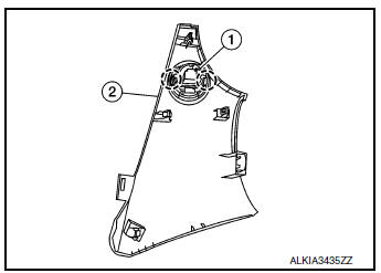
Exploded View
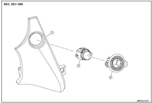
- Instrument finisher B
- Push button ignition switch
- NATS antenna amp.
 Pawl
Pawl
Removal and Installation
REMOVAL
- Remove the instrument finisher B. Refer to IP-16, "INSTRUMENT FINISHER B : Removal and Installation".
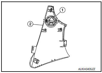
- Release pawls and remove NATS antenna amp. (1) from instrument finisher B (2).
: Pawl
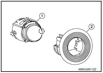
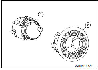
- Release pawls and remove NATS antenna amp. (2) from push
button ignition switch (1).: Pawl
INSTALLATION
Installation is in the reverse order of removal.
PUSH-BUTTON IGNITION SWITCH
Exploded View
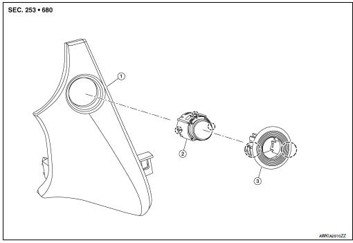
- Instrument finisher B
- Push button ignition switch
- NATS antenna amp.
Pawl
Removal and Installation
REMOVAL
- Remove the instrument finisher B. Refer to IP-16, "INSTRUMENT FINISHER B : Removal and Installation".
- Release pawls and remove NATS antenna amp. (1) from instrument
finisher B (2).: Pawl
- Release pawls and remove NATS antenna amp. (2) from push
button ignition switch (1).: Pawl
INSTALLATION
Installation is in the reverse order of removal.
 Symptom diagnosis
ENGINE DOES NOT START WHEN INTELLIGENT KEY IS INSIDE OF VEHICLE
Description
Engine does not start when push-button ignition switch is pressed while
carrying Intelligent Key.
NOTE:
Check ...

Other materials:
VDC warning lamp
Component Function Check
1.CHECK VDC WARNING LAMP FUNCTION
Check that VDC warning lamp in combination meter turns ON for 1 second after
ignition switch is turned ON.
CAUTION:
Never start the engine.
Is the inspection result normal?
YES >> Inspection End.
NO >> Proceed to BRC ...
P0451 EVAP control system pressure sensor
DTC Description
DTC DETECTION LOGIC
DTC No.
CONSULT screen terms
(Trouble diagnosis content)
DTC detecting condition
P0451
EVAP SYS PRES SEN
(Evaporative emission system pressure
sensor/switch range/performance)
ECM detects a sloshing signal from the EVAP contr ...
Towing recommended by NISSAN
All-Wheel Drive (AWD) models
NISSAN recommends that towing dollies be
used when towing your vehicle or the vehicle be
placed on a flatbed truck as illustrated.
CAUTIONDO NOT tow AWD models with any of the
wheels on the ground as this may cause
serious and expensive damage to the ...
