Nissan Rogue Service Manual: P0453 EVAP control system pressure sensor
DTC Description
DTC DETECTION LOGIC
| DTC No. | CONSULT screen terms (Trouble diagnosis content) | DTC detecting condition |
| P0453 | EVAP SYS PRES SEN (Evaporative emission system pressure sensor/switch high) | An excessively high voltage from the sensor is sent to ECM. |
POSSIBLE CAUSE
- Harness or connectors (EVAP control system pressure sensor circuit is shorted.)
- EVAP control system pressure sensor
FAIL-SAFE
Not applicable
DTC CONFIRMATION PROCEDURE
1.PRECONDITIONING
If DTC Confirmation Procedure has been previously conducted, always perform the following procedure before conducting the next test.
- Turn ignition switch OFF and wait at least 10 seconds.
- Turn ignition switch ON.
- Turn ignition switch OFF and wait at least 10 seconds.
TESTING CONDITION: Always perform test at a temperature of 5┬░C (41┬░F) or more.
>> GO TO 2.
2.PERFORM DTC CONFIRMATION PROCEDURE
 With CONSULT
- Start engine and warm it up to normal operating temperature.
- Turn ignition switch OFF and wait at least 10 seconds.
- Turn ignition switch ON.
- Select ÔÇťDATA MONITORÔÇŁ mode of ÔÇťENGINEÔÇŁ using CONSULT.
- Make sure that ÔÇťFUEL T/TMP SEÔÇŁ indication is more than 0┬░C (32┬░F).
- Start engine and wait at least 20 seconds.
- Check 1st trip DTC.
 With GST
- Start engine and warm it up to normal operating temperature.
- Set voltmeter probes to ECM harness connector terminals as per the following.
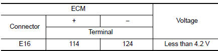
- Make sure that the voltage is less than 4.2 V.
- Turn ignition switch OFF and wait at least 10 seconds.
- Start engine and wait at least 20 seconds.
- Check 1st trip DTC.
Is 1st trip DTC detected? YES >> Proceed to EC-335, "Diagnosis Procedure".
NO >> INSPECTION END
Diagnosis Procedure
1.CHECK EVAP CONTROL SYSTEM PRESSURE SENSOR CONNECTOR FOR WATER
- Turn ignition switch OFF.
- Disconnect EVAP control system pressure sensor harness connector.
- Check sensor harness connector for water.
Water should not exist.
Is the inspection result normal? YES >> GO TO 2.
NO >> Repair or replace harness connector.
2.CHECK EVAP CONTROL SYSTEM PRESSURE SENSOR POWER SUPPLY
- Turn ignition switch ON.
- Check the voltage between EVAP control system pressure sensor harness connector and ground.
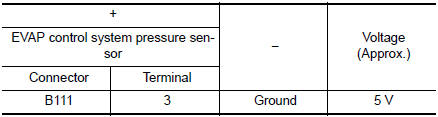
Is the inspection result normal? YES >> GO TO 4.
NO >> GO TO 3.
3.CHECK EVAP CONTROL SYSTEM PRESSURE SENSOR POWER SUPPLY CIRCUIT
- Turn ignition switch OFF.
- Disconnect ECM harness connector.
- Check the continuity between EVAP control system pressure sensor harness connector and ECM harness connector.
- Also check harness for short to ground and to power.
Is the inspection result normal? YES >> Perform the trouble diagnosis for power supply circuit.
NO >> Repair or replace error-detected parts
4.CHECK EVAP CONTROL SYSTEM PRESSURE SENSOR GROUND CIRCUIT
- Turn ignition switch OFF.
- Disconnect ECM harness connector.
- Check the continuity between EVAP control system pressure sensor harness connector and ECM harness connector.
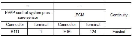
- Also check harness for short to power.
Is the inspection result normal? YES >> GO TO 5.
NO >> Repair or replace error-detected parts.
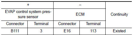
5.CHECK EVAP CONTROL SYSTEM PRESSURE SENSOR SIGNAL CIRCUIT
- Check the continuity between EVAP control system pressure sensor harness connector and ECM harness connector.
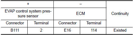
- Also check harness for short to ground and to power.
Is the inspection result normal? YES >> GO TO 6.
NO >> Repair or replace error-detected parts.
6.CHECK RUBBER TUBE
1. Disconnect rubber tube connected to EVAP canister vent control valve.
2. Check the rubber tube for clogging.
Is the inspection result normal? YES >> GO TO 7.
NO >> Clean the rubber tube using an air blower, repair or replace rubber tube.
7.CHECK EVAP CANISTER VENT CONTROL VALVE
Refer to EC-321, "Component Inspection".
Is the inspection result normal? YES >> GO TO 8.
NO >> Replace EVAP canister vent control valve. Refer to FL-21, "Removal and Installation".
8.CHECK EVAP CONTROL SYSTEM PRESSURE SENSOR
Refer to EC-337, "Component Inspection".
Is the inspection result normal? YES >> GO TO 9.
NO >> Replace EVAP control system pressure sensor. Refer to FL-22, "Removal and Installation".
9.CHECK IF EVAP CANISTER IS SATURATED WITH WATER
- Remove EVAP canister with EVAP canister vent control valve and EVAP control system pressure sensor attached.
- Check if water will drain from the EVAP canister.
Does water drain from EVAP canister? YES >> GO TO 10.
NO >> GO TO 12.
10.CHECK EVAP CANISTER
Weigh the EVAP canister with the EVAP canister vent control valve and EVAP control system pressure sensor attached.
The weight should be less than 1.9 kg (4.2 lb).
Is the inspection result normal? YES >> GO TO 12.
NO >> GO TO 11.
11.DETECT MALFUNCTIONING PART
Check the following.
- EVAP canister for damage
- EVAP hose between EVAP canister and vehicle frame for clogging or poor connection
>> Repair hose or replace EVAP canister. Refer to FL-19, "Removal and Installation".
12.CHECK INTERMITTENT INCIDENT
Refer to GI-41, "Intermittent Incident".
>> INSPECTION END
Component Inspection
1.CHECK EVAP CONTROL SYSTEM PRESSURE SENSOR
- Turn ignition switch OFF.
- Remove EVAP control system pressure sensor with its harness
connector connected from EVAP canister.
Always replace O-ring with a new one.
- Install a vacuum pump to EVAP control system pressure sensor.
- Turn ignition switch ON and check output voltage between ECM harness connector and ground under the following conditions.
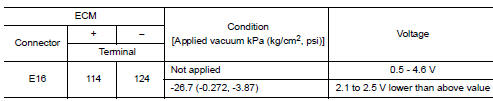
CAUTION:
- Always calibrate the vacuum pump gauge when using it.
- Do not apply below -93.3 kPa (-0.952 kg/cm2, -13.53 psi) or pressure over 101.3 kPa (1.033 kg/ cm2, 14.69 psi).
Is the inspection result normal? YES >> INSPECTION END
NO >> Replace EVAP control system pressure sensor. Refer to FL-22, "Removal and Installation".
 P0452 EVAP control system pressure sensor
DTC Description
DTC DETECTION LOGIC
DTC No.
CONSULT screen terms
(Trouble diagnosis content)
DTC detecting condition
P0452
EVAP SYS PRES SEN
(Evaporative emission syst ...
 P0456 EVAP control system
DTC Description
DTC DETECTION LOGIC
This diagnosis detects leaks in the EVAP line between fuel tank and EVAP
canister purge volume control solenoid
valve, using the negative pressure caused by de ...
Other materials:
Securing the load
Cargo area luggage hooks
There are luggage hooks located in the cargo
area as shown. The hooks can be used to secure
cargo with ropes or other types of straps.
Do not apply a total load of more than
6.5 lbs. (29 N) to a single metal floor hook
when securing cargo.
WARNING
&nb ...
Precaution
Precaution for Supplemental Restraint System (SRS) "AIR BAG" and "SEAT
BELT
PRE-TENSIONER"
The Supplemental Restraint System such as ÔÇťAIR BAGÔÇŁ and ÔÇťSEAT BELT PRE-TENSIONERÔÇŁ,
used along
with a front seat belt, helps to reduce the risk or severity of injury to the
...
How to erase permanent DTC
Description
OUTLINE
When a DTC is stored in ECM
When a DTC is stored in ECM and MIL is ON, a permanent DTC is erased with MIL
shutoff if the same malfunction
is not detected after performing the driving pattern for MIL shutoff three times
in a raw.
*1: When the same malfunction is detecte ...
