Nissan Rogue Service Manual: Moonroof motor assembly
Exploded View
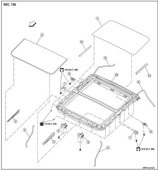
- Panoramic roof glass
- Glass lid
- Side trim covers (LH/RH)
- Front drain hose front (LH/RH)
- Moonroof motor assembly
- Sunshade motor assembly
- Moonroof front bracket (LH/RH)
- Moonroof rear bracket (LH/RH)
- Drain hose rear (LH/RH)
- Moonroof unit assembly
- Rear trim (LH/RH)
 Front
Front
Removal and Installation
REMOVAL
- Close glass lid.
- Remove the headlining. Refer to INT-30, "Removal and Installation".
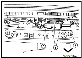
- Remove moonroof motor assembly screws (1).Front
- Disconnect harness connector (A) and remove moonroof motor
assembly (2) from moonroof unit assembly front end rail.
CAUTION: Do not run the removed moonroof motor assembly as a single unit.
INSTALLATION
- Move moonroof motor assembly laterally little by little so that the
gear is completely engaged into the wire
on the moonroof unit assembly, and the mounting surfaces become parallel.
Install the moonroof motor
assembly screws and tighten.
CAUTION: Before installing the motor, be sure to place the link and wire assembly in the symmetrical and fully closed position.
NOTE: If necessary, insert a suitable tool into the drive key and rotate right or left slightly to assist in complete moonroof motor gear alignment.
- Remainder of installation is in the reverse order of removal.
- Synchronize moonroof motor assembly with moonroof unit assembly. Refer to RF-24, "ADDITIONAL SERVICE WHEN REPLACING CONTROL UNIT : Special Repair Requirement".
 Panoramic roof glass
Exploded View
Panoramic roof glass
Glass lid
Side trim covers (LH/RH)
Front drain hose (LH/RH)
Moonroof motor assembly
Sunshade motor assembly
Moonroof front bracke ...
 Moonroof unit assembly
Inspection
WIND DEFLECTOR
Open glass lid fully.
Visually check for proper installation, damaged/deteriorated components,
or foreign objects within mechanism.
Correct as required for smooth ...
Other materials:
System
System Description
When the vehicle has reached a speed of 40 km/h (25 MPH) or greater, the BCM
receives a signal transmitted
from the tire pressure sensors installed in each wheel. If the BCM detects low
inflation pressure or a system
malfunction, it sends a signal to the combination meter v ...
Fuel pressure
Work Procedure
FUEL PRESSURE RELEASE
1.FUEL PRESSURE RELEASE
With CONSULT
Turn ignition switch ON.
Perform ŌĆ£FUEL PRESSURE RELEASEŌĆØ in ŌĆ£WORK SUPPORTŌĆØ mode of ŌĆ£ENGINEŌĆØ
using CONSULT.
Start engine.
After engine stalls, crank it two or three times to ...
Precaution
Precaution for Supplemental Restraint System (SRS) "AIR BAG" and "SEAT
BELT
PRE-TENSIONER"
The Supplemental Restraint System such as ŌĆ£AIR BAGŌĆØ and ŌĆ£SEAT BELT PRE-TENSIONERŌĆØ,
used along
with a front seat belt, helps to reduce the risk or severity of injury to the
...
