Nissan Rogue Service Manual: Fuel level sensor signal circuit
Component Function Check
1.COMBINATION METER INPUT SIGNAL
- Select "METER/M&A" on "CONSULT".
- Using "FUEL METER" of "Data Monitor", compare the value of "Data Monitor" with fuel gauge pointer of combination meter.
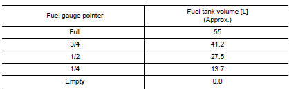
Does the data monitor value approximately match the fuel gauge indication? YES >> Inspection End.
NO >> Replace combination meter. Refer to MWI-82, "Removal and Installation".
Diagnosis Procedure
1.CHECK FUEL LEVEL SENSOR UNIT AND FUEL PUMP (FUEL LEVEL SENSOR) CIRCUIT
- Turn ignition switch OFF.
- Disconnect combination meter connector and fuel level sensor unit and fuel pump (fuel level sensor) connector.
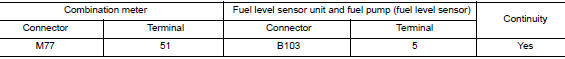
- Check continuity between combination meter harness connector and fuel level sensor unit and fuel pump (fuel level sensor) harness connector.
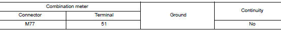
- Check continuity between combination meter harness connector and ground.
Is the inspection result normal? YES >> GO TO 2.
NO >> Repair harness or connector.
2.CHECK FUEL LEVEL SENSOR UNIT AND FUEL PUMP (FUEL LEVEL SENSOR) GROUND CIRCUIT
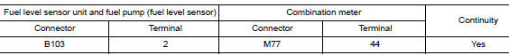
Check continuity between fuel level sensor unit and fuel pump (fuel level sensor) harness connector and combination meter harness connector.
Is the inspection result normal? YES >> Replace combination meter. Refer to MWI-82, "Removal and Installation".
NO >> Repair harness or connector.
Component Inspection
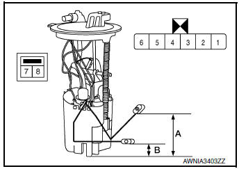
1.CHECK FUEL LEVEL SENSOR UNIT AND FUEL PUMP (FUEL LEVEL SENSOR)
- Remove the fuel level sensor unit and fuel pump (fuel level sensor). Refer to FL-6, "Removal and Installation".
- Check the resistance between fuel level sensor unit and fuel pump (fuel level sensor).
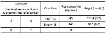
*: When float rod is contact with stopper.
Is the inspection result normal? YES >> GO TO 2.
NO >> Replace fuel level sensor unit and fuel pump (fuel level sensor). Refer to FL-6, "Removal and Installation".
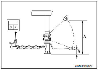
2.CHECK FUEL LEVEL SENSOR UNIT (SUB)
- Remove the fuel level sensor unit (sub). Refer to FL-6, "Removal and Installation".
- Check the resistance between fuel level sensor unit (sub).
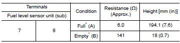
*: When float rod is contact with stopper.
Is the inspection result normal? YES >> Inspection End.
NO >> Replace fuel level sensor unit (sub). Refer to FL-6, "Removal and Installation".
 Power supply and ground circuit
COMBINATION METER
COMBINATION METER : Diagnosis Procedure
Regarding Wiring Diagram information, refer to MWI-32, "Wiring Diagram".
1.CHECK FUSES
Check that the following fuses are not bl ...
 Parking brake switch signal circuit
Description
Transmits the parking brake switch signal to the combination meter.
Component Function Check
1.COMBINATION METER INPUT SIGNAL
Start engine.
Check "PKB SW" in ...
Other materials:
Front wiper drive assembly
Exploded View
REMOVAL
Cowl top
Front wiper drive assembly
Removal and Installation
REMOVAL
Remove cowl top cover. Refer to EXT-25, "Removal and
Installation".
Disconnect harness connector from front wiper motor.
Remove bolts and front wiper driv ...
U1010 control unit (CAN)
Description
Air bag diagnosis sensor performs self-tests on key ON. If CAN communication
failure within control unit is
detected, DTC is set.
DTC Logic
DTC DETECTION LOGIC
CONSULT name
DTC
DTC detecting condition
Repair order
CAN CONTROL UNIT FAILURE
...
System description
STRUCTURE AND OPERATION
Sectional View
Drive gear
Side bearing
Differential case
Pinion mate shaft
Side gear
Pinion mate gear
Drive pinion
Collapsible spacer
AWD solenoid
Stud bolt
Electric controlled coupling
Pinion front bearing
Pinion rear bearing
Elect ...
