Nissan Rogue Service Manual: Front wiper does not operate
Description
The front wiper does not operate under any operation conditions.
Diagnosis Procedure
Regarding Wiring Diagram information, refer to WW-22, "Wiring Diagram".
1. CHECK WIPER RELAY OPERATION
 CONSULT ACTIVE TEST
- Select FR WIPER of BCM (WIPER) active test item.
- Check front wiper operation.
LO : Front wiper LO operation
HI : Front wiper HI operation
OFF : Front wiper stop
Is the inspection result normal? YES >> GO TO 5.
NO >> GO TO 2.
2. CHECK FRONT WIPER MOTOR FUSE
Refer to WW-35, "Diagnosis Procedure".
Is the fuse blown? YES >> Replace the fuse after repairing the affected circuit.
NO >> GO TO 3.
3. CHECK FRONT WIPER MOTOR GROUND CIRCUIT
Refer to WW-42, "Diagnosis Procedure".
Is the inspection result normal? YES >> GO TO 4.
NO >> Repair or replace harness.
4. CHECK FRONT WIPER MOTOR OUTPUT VOLTAGE
- Turn the ignition switch ON.
- With CONSULT, select FRONT WIPER of IPDM E/R ACTIVE TEST item.
- Check voltage between IPDM E/R harness connector and ground while wipers are operating.
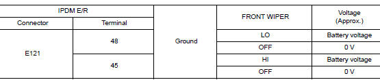
Is the inspection result normal? YES >> Replace front wiper motor. Refer to WW-67, "Removal and Installation".
NO >> Replace IPDM E/R. Refer to PCS-35, "Removal and Installation".
5. CHECK FRONT WIPER REQUEST SIGNAL INPUT
- With CONSULT, select FR WIP REQ in DATA MONITOR of IPDM E/R.
- Switch the front wiper switch to HI and LO.
- Check the status of FR WIP REQ while operating the switch.
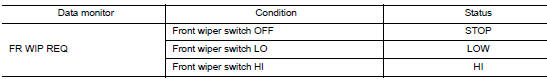
Is the inspection result normal? YES >> Replace IPDM E/R. Refer to PCS-35, "Removal and Installation" .
NO >> GO TO 6.
6. CHECK COMBINATION SWITCH (WIPER AND WASHER SWITCH)
Check combination switch (wiper and washer switch). Refer to WW-45, "Component Inspection".
Is the inspection result normal? YES >> Replace BCM. Refer to BCS-75, "Removal and Installation" (with Intelligent Key system) or BCS- 135, "Removal and Installation" (without Intelligent Key system).
NO >> Repair or replace the applicable parts.
 Wiper and washer system symptoms
Symptom Table
CAUTION:
Perform the self-diagnosis with CONSULT before performing the diagnosis by
symptom. Perform the
diagnosis by DTC if DTC is detected.
...
 Normal operating condition
Description
FRONT WIPER PROTECTION FUNCTION
IPDM E/R detects front wiper stop position by a front wiper stop position
signal.
When a front wiper stop position signal is in the conditions listed ...
Other materials:
Precaution
Precaution for Supplemental Restraint System (SRS) "AIR BAG" and "SEAT
BELT
PRE-TENSIONER"
The Supplemental Restraint System such as “AIR BAG” and “SEAT BELT PRE-TENSIONER”,
used along
with a front seat belt, helps to reduce the risk or severity of injury to the
...
Sensor power supply2 circuit
Description
ECM supplies a voltage of 5 V to some of the sensors systematically divided
into 2 groups, respectively.
Accordingly, when a short circuit develops in a sensor power source, a
malfunction may occur simultaneously
in the sensors belonging to the same group as the short-circuited ...
Exterior front
Front view camera (if so equipped)
Engine hood
Windshield wiper and washer switch, wiper blades
Windshield-washer fluid
Windshield
Power windows
Door locks, NISSAN Intelligent Key® (if so equipped), NISSAN Jackknife
key (if so equipped), key ...
