Nissan Rogue Service Manual: Engine coolant
Inspection
LEVEL
- Check that the reservoir tank engine coolant level is within the “MIN” to “MAX” when the engine is cool.
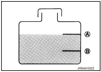
(A) : MAX
(B) : MIN
- Adjust the engine coolant level if necessary.
CAUTION: Refill Genuine NISSAN Long Life Antifreeze/Coolant (blue) or equivalent in its quality mixed with water (distilled or demineralized).
Refer to MA-11, "Fluids and Lubricants".
CHECKING COOLING SYSTEM FOR LEAKS
- To check for leaks, apply pressure to the cooling system using suitable tools (A/B).
Testing pressure : Refer to CO-25, "Radiator".
WARNING: Do not remove the radiator cap when the engine is hot. Serious burns could occur from high-pressure engine coolant escaping from the radiator. Wrap a thick cloth around the cap.
Slowly push down and turn it a quarter turn to allow built-up pressure to escape. Carefully remove the cap by pushing it down and turning it all the way.
CAUTION:
- Perform this step when the engine is cold.
- Do not spill engine coolant on drivebelt.
- Higher test pressure than specified may cause radiator damage.
NOTE:
- If engine coolant decreases, replenish radiator with engine coolant. Refer to MA-11, "Fluids and Lubricants".
- If anything is found, repair or replace damaged parts.
Draining
WARNING: Do not remove radiator cap when engine is hot. Serious burns could occur from high pressure engine coolant escaping the radiator. Wrap a thick cloth around the cap. Slowly push down and turn it a quarter turn to allow built-up pressure to escape. Carefully remove the cap by pushing it down and turning it all the way.
- Open radiator drain plug at the bottom of radiator, and then remove radiator cap.
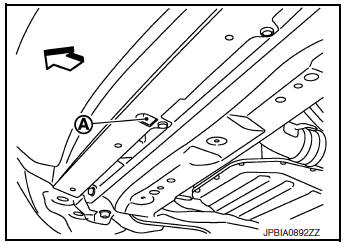
(A) : Radiator drain plug hole
 : Vehicle front
CAUTION:
- Do not allow engine coolant to contact the drive belt.
- Perform this step when the engine is cold.
- Follow this step for heater core removal/replacement only. Disconnect the upper heater hose at the engine side and apply moderate air pressure [103.46 kPa (1.055 kg/cm2, 15 psi) maximum air pressure] into the hose for 30 seconds to blow the excess engine coolant out of the heater core.
- When draining all of the engine coolant in the system, remove the reservoir tank and drain the engine coolant, then clean the reservoir tank before installation.
CAUTION:
- Do not allow the engine coolant to contact the drive belt.
- Perform this step when engine is cold.
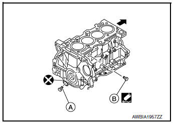
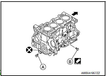
- When draining all of the engine coolant in the system for engine removal or repair, remove the engine coolant drain plugs (A/B) from the cylinder block.
- Check the drained engine coolant for contaminants such as rust,
corrosion or discoloration.
If the engine coolant is contaminated, flush the engine cooling system. Refer to CO-11, "Flushing".
Refilling
CAUTION:
- Do not put additive such as waterleak preventive, since it may cause cooling waterway clogging.
- When refilling use Genuine NISSAN Long Life Antifreeze/Coolant (blue) or equivalent in its quality mixed with water (distilled or demineralized). Refer to MA-11, "Fluids and Lubricants".
- Install the radiator drain plug. Install the reservoir tank and cylinder block drain plug, if removed for a total system drain or for engine removal or repair.
- The radiator must be completely empty of coolant and water.
- Apply sealant to the threads of the cylinder block drain plug.
- Use recommended coolant or equivalent.
Refer to MA-11, "Fluids and Lubricants".
Radiator drain plug : Refer to CO-13, "Exploded View".
Cylinder block drain plug (A) : 53.9 Nm (5.5 kg-m, 40 ft-lb)
Cylinder block drain plug (B) : 9.8 N·m (1.0 kg-m, 87 in-lb)
- If disconnected, reattach the upper radiator hose at the engine side.
- Set the vehicle heater controls to the full HOT and heater ON position. Turn the vehicle ignition ON with the engine OFF as necessary to activate the heater mode.
- Install the Tool by installing the radiator cap adapter onto the radiator neck opening. Then attach the gauge body assembly with the refill tube and the venturi assembly to the radiator cap adapter.
Tool number : KV991J0070 (J-45695)
- Insert the refill hose into the coolant mixture container that is placed at floor level. Make sure the ball valve is in the closed position.
- Use recommended coolant or equivalent.
Refer to MA-11, "Fluids and Lubricants".
Engine coolant capacity (with reservoir tank) : Refer to CO-25, "Periodical Maintenance Specification".
CAUTION:
Do not use any cooling system additives such as radiator sealer. Additives may clog the cooling system and cause damage to the engine, transmission and/or cooling system.
- Install an air hose to the venturi assembly, the air pressure must be within specification.
Compressed air supply pressure : 549 - 824 kPa (5.6 - 8.4 kg/cm2, 80 - 119 psi)
CAUTION: The compressed air supply must be equipped with an air dryer.
- The vacuum gauge will begin to rise and there will be an audible hissing noise. During this process open the ball valve on the refill hose slightly. Coolant will be visible rising in the refill hose. Once the refill hose is full of coolant, close the ball valve. This will purge any air trapped in the refill hose.
- Continue to draw the vacuum until the gauge reaches 28 inches of vacuum. The gauge may not reach 28 inches in high altitude locations, use the vacuum specifications based on the altitude above sea level.
Altitude above sea level Vacuum gauge reading
0 - 100 m (328 ft) : 28 inches of vacuum
300 m (984 ft) : 27 inches of vacuum
500 m (1,641 ft) : 26 inches of vacuum
1,000 m (3,281 ft) : 24 - 25 inches of vacuu
- When the vacuum gauge has reached the specified amount, disconnect the air hose and wait 20 seconds to see if the system loses any vacuum. If the vacuum level drops, perform any necessary repairs to the system and repeat steps 6 - 8 to bring the vacuum to the specified amount. Recheck for any leaks.
- Place the coolant container (with the refill hose inserted) at the
same level as the top of the radiator. Then
open the ball valve on the refill hose so the coolant will be drawn up to
fill the cooling system. The cooling
system is full when the vacuum gauge reads zero.
CAUTION: Do not allow the coolant container to get too low when filling, to avoid air from being drawn into the cooling system.
- Remove the Tool from the radiator neck opening.
- Fill the cooling system reservoir tank to the specified level and install the radiator cap. Run the engine to warm up the cooling system and top up the system as necessary.
Flushing
- Install reservoir tank, if removed, and radiator drain plug.
CAUTION:
- Be sure to clean drain plug.
- Do not reuse O-ring.
Radiator drain plug : Refer to CO-13, "Exploded View".
- If water drain plugs on cylinder block are removed, close and tighten them. Refer to EM-92, "Exploded View".
- Run the engine and warm it up to normal operating temperature.
- Rev the engine two or three times under no-load.
- Stop the engine and wait until it cools down.
- Drain water from the system. Refer to CO-8, "Draining".
- Repeat steps 1 through 5 until clear water begins to drain from radiator.

 Radiator
RADIATOR CAP
RADIATOR CAP : Inspection
CHECKING RADIATOR CAP
Inspect the radiator cap.
Replace the cap if the metal plunger cannot be seen around the
edge of the black rubbe ...
Other materials:
Driving safety precautions
Your NISSAN is designed for both normal and
off-road use. However, avoid driving in deep water
or mud as your NISSAN is mainly designed for
leisure use, unlike a conventional off-road vehicle.
Remember that two-wheel drive models are less
capable than all-wheel drive models for rough
road dr ...
Precaution
Precaution for Supplemental Restraint System
(SRS) "AIR BAG" and "SEAT BELT PRE-TENSIONER"
The Supplemental Restraint System such as “AIR BAG” and “SEAT BELT PRE-TENSIONER”,
used along
with a front seat belt, helps to reduce the risk or severity of injury to the
dr ...
Monitor, climate, audio, phone and voice recognition systems
WARNING
Positioning of the heating or air conditioning
controls and display controls
should not be done while driving in order
that full attention may be given to
the driving operation.
Do not disassemble or modify this system.
If you do, it may result ...
