Nissan Rogue Service Manual: Cooler pipe and hose
Exploded View
- Condenser
- High-pressure flexible hose
- Low-pressure flexible hose
- Low-pressure pipe
- Heating and cooling unit assembly
- High-pressure pipe
- Compressor
- O-ring
- Low-pressure service port
- High-pressure service port
LOW-PRESSURE PIP
LOW-PRESSURE PIPE : Removal and Installation
REMOVAL
- Discharge the refrigerant. Refer to HA-23, "Recycle Refrigerant".
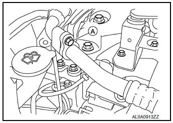
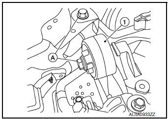
- Remove bolts (A) and engine upper mount (1).
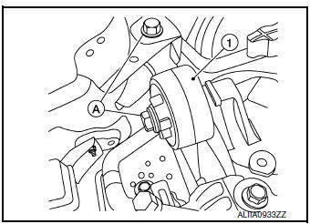
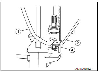
- Remove the bolt (A) that retains the low-pressure flexible hose to the low-pressure pipe.
CAUTION: Cap or wrap the joint of the pipe with suitable material such as vinyl tape to avoid the entry of air.
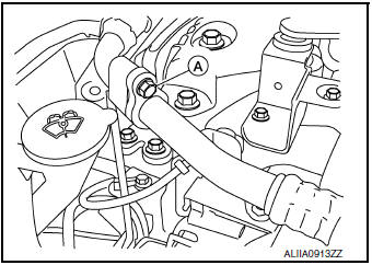
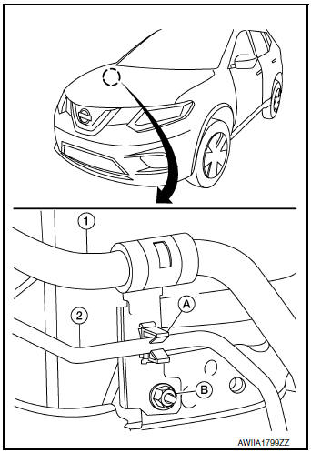
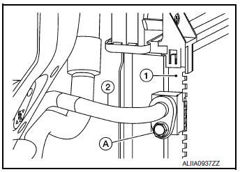
- Remove low-pressure pipe bracket bolts (A) and bracket.
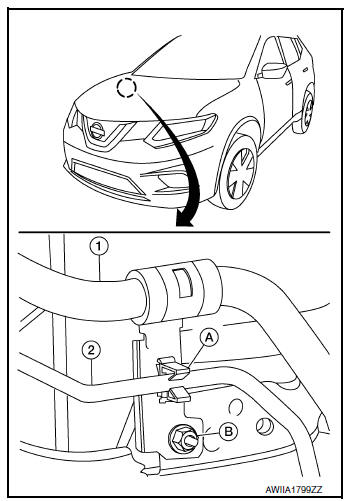
- Release high-pressure pipe (2) from clamp (A).
- Remove nut (B) and low-pressure pipe (1).
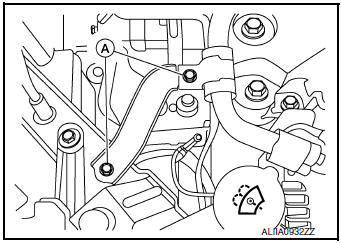
- Remove the bolt (A) that retains the low-pressure and high-pressure pipe to the expansion valve (1).
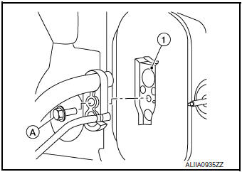
- Remove low-pressure pipe.
INSTALLATION
Installation is in the reverse order of removal.
CAUTION:
- Tighten bolts to specified torque. Refer to HA-32, "Exploded View".
- Do not reuse O-rings.
- Apply A/C oil to new O-rings for installation.
- After charging refrigerant, check for leaks. Refer to HA-21, "Leak Test".
LOW-PRESSURE FLEXIBLE HOSE
LOW-PRESSURE FLEXIBLE HOSE : Removal and Installation
REMOVAL
- Discharge the refrigerant. Refer to HA-23, "Recycle Refrigerant".
- Remove the bolt (A) that retains the low-pressure flexible hose to the low-pressure pipe.
CAUTION: Cap or wrap the joint of the pipe with suitable material such as vinyl tape to avoid the entry of air.
- Remove the nut (A) that retains the low-pressure flexible hose to the compressor.
- Remove the low-pressure flexible hose.
INSTALLATION
Installation is in the reverse order of removal.
CAUTION:
- Tighten nut/bolt to specified torque. Refer to HA-32, "Exploded View".
- Do not reuse O-rings.
- Apply A/C oil to new O-rings for installation.
- After charging refrigerant, check for leaks. Refer to HA-21, "Leak Test".
HIGH-PRESSURE PIPE
HIGH-PRESSURE PIPE : Removal and Installation
REMOVAL
- Discharge the refrigerant. Refer to HA-23, "Recycle Refrigerant".
- Remove front bumper fascia. Refer to EXT-17, "Removal and Installation".
- Remove air duct assembly. Refer to EM-24, "Exploded View".
- Remove bolts (A) and upper engine mount (1).
- Release high-pressure pipe (2) from clamp (A).
(1): Low-pressure pipe
(B): Nut
- Remove bolt (A) that retains high-pressure pipe (1) to the condenser
(2).
CAUTION: Cap or wrap the joint of the pipe with suitable material such as vinyl tape to avoid the entry of air.
- Remove the bolt (A) that retains the high-pressure and low-pressure pipe to the expansion valve (1).
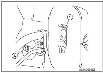
- Remove high-pressure pipe.
INSTALLATION
Installation is in the reverse order of removal.
CAUTION:
- Tighten bolts to specified torque. Refer to HA-32, "Exploded View".
- Do not reuse O-rings.
- Apply A/C oil to new O-rings for installation.
- After charging the refrigerant, check for leaks. Refer to HA-21, "Leak Test".
HIGH-PRESSURE FLEXIBLE HOSE
HIGH-PRESSURE FLEXIBLE HOSE : Removal and Installation
REMOVAL
- Discharge the refrigerant. Refer to HA-23, "Recycle Refrigerant".
- Remove front bumper fascia. Refer to EXT-17, "Removal and Installation".
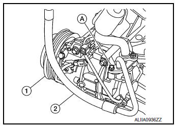
- Remove the bolt (A) that retains the high-pressure flexible hose (2) to the condenser (1).
CAUTION: Cap or wrap the joint of the pipe with suitable material such as vinyl tape to avoid the entry of air.
- Remove the bolt (A) that retains the high-pressure flexible hose (2) to the compressor (1).
INSTALLATION
Installation is in the reverse order of removal.
CAUTION:
- Tighten bolts to specified torque. Refer to HA-37, "Exploded View".
- Do not reuse O-rings.
- Apply A/C oil to new O-rings for installation.
- After charging the refrigerant, check for leaks. Refer to HA-21, "Leak Test".
 Compressor
Exploded View
Compressor
Removal and Installation
REMOVAL
Discharge the refrigerant. Refer to HA-23, "Recycle Refrigerant".
Remove the engine under cover. Refer to EX ...
 Condenser
Exploded View
Air guide (LH)
Condenser upper bracket (LH)
Condenser (includes liquid tank)
Condenser upper bracket (RH)
Air guide (RH)
Refrigerant pressure sensor
C ...
Other materials:
Periodic maintenance
FRONT SUSPENSION ASSEMBLY
Inspection
COMPONENT
Check the conditions (looseness, backlash) of each component. Verify the
component conditions (wear, damage)
are normal.
Ball Joint Axial End Play
Set front wheels in a straight-ahead position.
Move axle side of transverse link, ...
Wheel alignment
Inspection
DESCRIPTION
Measure wheel alignment under unladen conditions.
NOTE:
тАЬUnladen conditionsтАЭ means that fuel, engine coolant, and lubricants are
full. Spare tire, jack, hand tools and
mats are in designated positions.
PRELIMINARY CHECK
Check the following:
&nbs ...
P1212 TCS communication line
Description
This CAN communication line is used to control the smooth engine operation
during the TCS operation. Pulse
signals are exchanged between ECM and тАЬABS actuator and electric unit (control
unit)тАЭ.
Be sure to erase the malfunction information such as DTC not only for тАЬABS
ac ...
