Nissan Rogue Service Manual: Compressor
Exploded View

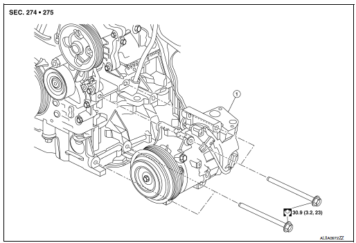
- Compressor
Removal and Installation
REMOVAL
- Discharge the refrigerant. Refer to HA-23, "Recycle Refrigerant".
- Remove the engine under cover. Refer to EXT-37, "ENGINE UNDER COVER : Removal and Installation".
- Release the drive belt from the compressor. Refer to EM-13,
"Removal and Installation".
NOTE: Complete removal of the drive belt is not necessary.
- Partially remove the front fender protector (RH). Refer to EXT-28, "FENDER PROTECTOR : Removal and Installation".
- Remove the nut (A) that retains the low-pressure flexible hose to
the compressor.
CAUTION: Cap or wrap the joint of the pipe with suitable material such as vinyl tape to avoid the entry of air.

- Remove the bolt (A) that retains the high-pressure flexible hose (2) to the compressor (1).

- Disconnect the harness connectors from the compressor.
- Remove bolts and compressor.
INSTALLATION
Installation is in the reverse order of removal.
CAUTION:
- Tighten nut/bolt to specification. Refer to HA-32, "Exploded View".
- Do not reuse O-rings.
- Apply A/C oil to new O-rings for installation.
- After charging refrigerant, check for leaks. Refer to HA-21, "Leak Test".
- After installation, check the tension of the drive belt. Refer to EM-13, "Checking".
 Cooler pipe and hose
Exploded View
Condenser
High-pressure flexible hose
Low-pressure flexible hose
Low-pressure pipe
Heating and cooling unit assembly
High-pressure pipe
Compressor
...
Other materials:
Preparation
Special Service Tool
The actual shape of the tools may differ from those illustrated here
Tool number
(TechMate No.)
Tool name
Description
—
(J-46534)
Trim Tool Set
Removing trim components
Commercial Service Tools
Tool name
...
Precaution
Precaution for Supplemental Restraint System (SRS) "AIR BAG" and "SEAT
BELT
PRE-TENSIONER"
The Supplemental Restraint System such as “AIR BAG” and “SEAT BELT PRE-TENSIONER”,
used along
with a front seat belt, helps to reduce the risk or severity of injury to the
...
DTC/circuit diagnosis
U0428 STEERING ANGLE SENSOR
DTC Logic
DTC DETECTION LOGIC
CONSULT Display
DTC Detection Condition
Possible Cause
ST ANG SEN CALIB
[U0428]
The neutral position adjustment of the steering
angle sensor is incomplete.
Adjust neutral position of the steeri ...

