Nissan Rogue Service Manual: Brake pedal
Adjustment
BRAKE PEDAL HEIGHT
- Remove instrument lower panel LH. Refer to IP-22, "Removal and Installation".
- Disconnect the harness connectors from the stop lamp switch and brake pedal position switch.
- Turn the stop lamp switch and brake pedal position switch 45┬░ counterclockwise.
- Check that the brake pedal height meets the specification by checking the brake pedal and brake booster for damage and replace parts as necessary. Refer to BR-54, "Brake Pedal".
- Turn the stop lamp switch and brake pedal position switch 45┬░ clockwise.
- Connect the harness connectors to the stop lamp switch and brake pedal position switch.
- Check the brake pedal for smooth operation.
CAUTION: The stop lamp must turn off when the brake pedal is released.
STOP LAMP SWITCH AND BRAKE PEDAL POSITION SWITCH
- Remove instrument lower panel LH. Refer to IP-22, "Removal and Installation".
- Disconnect the harness connectors from the stop lamp switch and brake pedal position switch.
- Turn the stop lamp switch and brake pedal position switch 45┬░ counterclockwise.
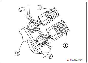
- With the threaded ends of the stop lamp switch (3) and brake
pedal position switch (1) contacting the brake pedal stopper
bracket (2), turn the switches 45┬░ clockwise to lock in place.
Check that both the stop lamp switch (3) and brake pedal position switch (1) contact ends to brake pedal stopper bracket (2) clearance (A) are within specification.
CAUTION:
- Make sure that the clearance (A) between the brake pedal stopper bracket (2), stop lamp switch (3) and the brake pedal position switch (1) contact ends are within specification.
- The stop lamp must turn off when the brake pedal is released.

Clearance (A) : Refer to BR-54, "Brake Pedal".
 Brake fluid
Drain and Refill
CAUTION:
Do not spill or splash brake fluid on painted surfaces. Brake
fluid may damage paint. If brake fluid is
splashed on painted areas, wash it away with water imm ...
Other materials:
Seat belt extenders
3rd row shown; 2nd row similar
Seat belt hook
When the seat belt is not in use and when folding
down the rear seats, hook the rear seat belts on
the seat belt hooks.
If, because of body size or driving position, it is
not possible to properly fit the lap/shoulder belt
and fasten it, an ex ...
P0847 transmission fluid pressure SEN/SW B
DTC Description
DTC DETECTION LOGIC
DTC
CONSULT screen terms
(Trouble diagnosis content)
DTC detection condition
P0847
FLUID PRESS SEN/SW B
(Transmission Fluid Pressure Sensor/Switch B
Circuit Low)
When all of the following conditions are satisfied and this sta ...
Precaution]
Precaution for Supplemental Restraint System (SRS) "AIR BAG" and "SEAT
BELT
PRE-TENSIONER"
The Supplemental Restraint System such as ŌĆ£AIR BAGŌĆØ and ŌĆ£SEAT BELT PRE-TENSIONERŌĆØ,
used along
with a front seat belt, helps to reduce the risk or severity of injury to the
...

