Nissan Rogue Service Manual: Ambient sensor signal circuit
Description
It detects outside air temperature and converts it into a resistance value which is then input into the combination meter.
Diagnosis Procedure
Regarding Wiring Diagram information, refer to MWI-32, "Wiring Diagram".
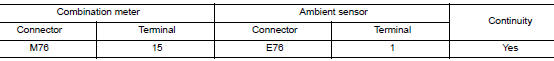
1.CHECK AMBIENT SENSOR SIGNAL CIRCUIT
- Turn ignition switch OFF.
- Disconnect combination meter connector and ambient sensor connector.
- Check continuity between combination meter harness connector and ambient sensor harness connector.
- Check continuity between combination meter harness connector and ground.
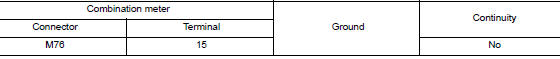
Is the inspection result normal? YES >> GO TO 2.
NO >> Repair or replace harness or connector.
2.CHECK AMBIENT SENSOR SIGNAL GROUND CIRCUIT
Check continuity between combination meter harness connector and ambient sensor harness connector.
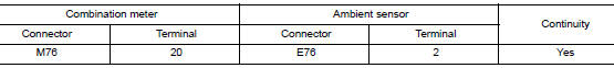
Is the inspection result normal? YES >> Inspection End.
NO >> Repair or replace harness or connector.
Component Inspection
1.CHECK AMBIENT SENSOR
- Turn ignition switch OFF.
- Disconnect ambient sensor connector.
- Check resistance between ambient sensor terminals.
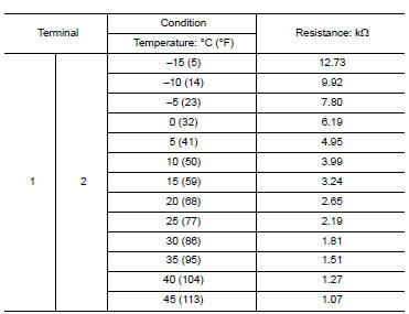
Is the inspection result normal? YES >> Inspection End.
NO >> Replace ambient sensor. Refer to HAC-104, "Removal and Installation".
 Parking brake switch signal circuit
Description
Transmits the parking brake switch signal to the combination meter.
Component Function Check
1.COMBINATION METER INPUT SIGNAL
Start engine.
Check "PKB SW" in ...
 Meter control switch signal circuit
Diagnosis Procedure
Regarding Wiring Diagram information, refer to MWI-32, "Wiring Diagram".
1.CHECK METER CONTROL SWITCH SIGNAL
Turn ignition switch ON.
Check voltage be ...
Other materials:
P2813 select solenoid
DTC Description
DTC DETECTION LOGIC
DTC
CONSULT screen terms
(Trouble diagnosis content)
DTC detection condition
P2813
SELECT SOLENOID
(Select solenoid)
When any of 1, or 2 is satisfied:
When all the following conditions are established three
times ...
Parking brake switch signal circuit
Description
Transmits the parking brake switch signal to the combination meter.
Component Function Check
1.COMBINATION METER INPUT SIGNAL
Start engine.
Check "PKB SW" in "Data Monitor" while applying and releasing the
parking brake.
Is the inspectio ...
Symptom diagnosis
SQUEAK AND RATTLE TROUBLE DIAGNOSES
Work Flow
CUSTOMER INTERVIEW
Interview the customer if possible, to determine the conditions that exist
when the noise occurs. Use the Diagnostic
Worksheet during the interview to document the facts and conditions when the
noise occurs and any
custome ...
