Nissan Rogue Owners Manual: Active ride control
This system senses upper body motion (based on wheel speed information) and controls engine torque and four wheel brake pressure. This will enhance ride comfort in effort to restrain uncomfortable upper body movement when passing over undulated road surfaces . This system comes into effect above 25 mph (40 km/h).
When the VDC OFF switch is used to turn off the VDC system, the Active Ride Control is also turned off.
Active ride control
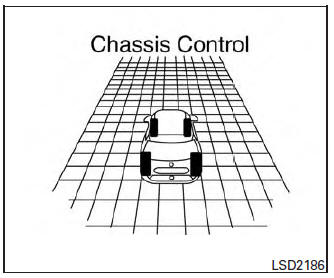
When brake control of Active Ride Control is operated and the “Chassis Control” mode is selected in the trip computer, the Active Ride Control graphics are shown in the vehicle information display. For additional information, refer to “Trip Computer” in the “Instruments and Controls” section of this manual.
If the chassis control warning message appears in the vehicle information display, it may indicate that the Active Ride Control is not functioning properly. Have the system checked by a NISSAN dealer as soon as possible.
When the Active Ride Control is operating, you may hear noise and sense slight deceleration.
This is normal and indicates that the Active Ride Control is operating properly.
 Active engine brake
The Active Engine Brake function adds subtle
deceleration by controlling CVT gear ratio, depending
on the cornering condition calculated
from driver’s steering input and plural sensors.
This b ...
 Hill Descent Control System (if so equipped)
Hill Descent Control System
WARNING
Never rely solely on the hill descent
control system to control vehicle speed
when driving on steep downhill grades.
Always drive ...
Other materials:
Moonroof switch
Removal and Installation
REMOVAL
Remove map lamp assembly. Refer to INL-55, "Removal and Installation".
Using a suitable tool release clip from harness connector.
: Clip
Using a suitable tool release pawls and remove moonroof switch
finisher (1).
Using a ...
Wiring diagram
ENGINE START FUNCTION
Wiring Diagram
NISSAN VEHICLE IMMOBILIZER SYSTEM-NATS
Wiring Diagram
VEHICLE SECURITY SYSTEM
Wiring Diagram
...
Remote keyless entry system (if so equipped)
WARNING
Radio waves could adversely affect
electric medical equipment. Those who
use a pacemaker should contact the
electric medical equipment manufacturer
for the possible influences before
use.
The remote keyless entry keyfob transmits
radio waves ...
