Nissan Rogue Service Manual: Wheel alignment
Inspection
DESCRIPTION
- Measure wheel alignment under unladen conditions.
NOTE: ŌĆ£Unladen conditionsŌĆØ means that fuel, engine coolant, and lubricants are full. Spare tire, jack, hand tools and mats are in designated positions.
PRELIMINARY CHECK
Check the following:
- Tires for improper air pressure and wear. Refer to WT-65, "Tire Air Pressure".
- Wheels for runout, deformation, cracks, or other damage. Refer to WT-56, "Inspection".
- Wheel bearings for axial end play. Refer to RAX-8, "Inspection" (FWD), RAX-18, "Inspection" (AWD).
- Shock absorbers for proper operation.
- Each suspension component for cracks, looseness, deformation, and other damages.
- Wheelarch height. Refer to RSU-24, "Wheelarch Height (Unladen*)".
GENERAL INFORMATION AND RECOMMENDATIONS
- A four-wheel thrust alignment should be performed.
- This type of alignment is recommended for any NISSAN/INFINITI vehicle.
- The four-wheel ŌĆ£thrustŌĆØ process helps ensure that the vehicle is properly aligned and the steering wheel is centered.
- The alignment rack itself should be capable of accepting any NISSAN/INFINITI vehicle.
- The rack should be checked to ensure that it is level.
- Make sure the machine is properly calibrated.
- Your alignment equipment should be regularly calibrated in order to give correct information.
- Check with the manufacturer of your specific equipment for their recommended Service/Calibration Schedule.
ALIGNMENT PROCESS
IMPORTANT: Use only the alignment specifications listed in this Service Manual RSU-24, "Wheel Alignment (Unladen*1)".
- When displaying the alignment settings, many alignment machines use ŌĆ£indicatorsŌĆØ: (Green/red, plus or minus, Go/No Go). Do not use these indicators.
- The alignment specifications programmed into your machine that operate these indicators may not be correct.
- This may result in an ERROR.
- Most camera-type alignment machines are equipped with both ŌĆ£Rolling CompensationŌĆØ method and optional ŌĆ£Jacking CompensationŌĆØ method to ŌĆ£compensateŌĆØ the alignment targets or head units. ŌĆ£Rolling CompensationŌĆØ is the preferred method.
- If using the ŌĆ£Rolling CompensationŌĆØ method, after installing the alignment targets or head units, push or pull on the rear wheel to move the vehicle. Do not push or pull on the vehicle body.
- If using the ŌĆ£Jacking CompensationŌĆØ method, after installing the alignment targets or head units, raise the vehicle and rotate the wheels 1/2 turn both ways.
NOTE: Do not use the ŌĆ£Rolling CompensationŌĆØ method if you are using sensor-type alignment equipment.
- Follow all instructions for the alignment machine you're using for more information.
Adjustment
CAMBER
If camber is outside the standard value, adjust with adjusting bolt (1) in lower link (2).
Camber: Refer to RSU-6, "Adjustment".
CAUTION: After adjusting camber, be sure to check toe-in.
TOE-IN
- If toe-in is not within the specification, adjust with adjusting bolt (1) in suspension arm (2).
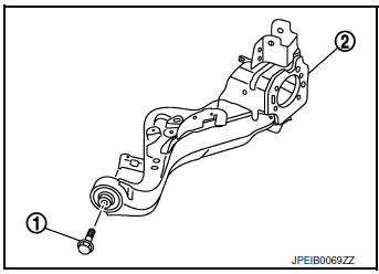
Toe-In: Refer to RSU-6, "Adjustment"
CAUTION:
- Be sure to adjust equally on RH and LH side with adjusting bolt.
- When tightening the nut firmly and checking the torque, use a wrench to prevent the turning of the bolt.
- If toe-in is not still within the specification, inspect and replace any damaged or worn suspension parts.
- - After toe-in adjustment, adjust neutral position of steering angle sensor. Refer to BRC-70, "Work Procedure".
 Rear suspension assembly
Inspection and Adjustment
COMPONENT PART
Check the conditions (looseness, backlash) of each component and component
conditions (wear, damage)
are normal.
SHOCK ABSORBER
Check the shock absorber ...

Other materials:
Front manual seat adjustment
(if so equipped)
Forward and backward
Pull the center of the bar up and hold it while you
slide the seat forward or backward to the desired
position. Release the bar to lock the seat in
position.
Reclining
To recline the seatback, pull the lever up and lean
back. To bring the seatback forward, pull the ...
Refrigeration system symptoms
Trouble Diagnosis For Unusual Pressure
Diagnose using a manifold gauge whenever systemŌĆÖs high and/or low side
pressure(s) is/are unusual. The
marker above the gauge scale in the following tables indicates the standard
(usual) pressure range. Refer to
above table (Ambient air temperature-to- ...
Symptom diagnosis
PUSH-BUTTON IGNITION SWITCH DOES NOT OPERATE
Description
Check that vehicle Operating Conditions are as listed in ŌĆ£Conditions of
VehicleŌĆØ below before starting Diagnosis
Procedure. Make sure to check each symptom in Diagnosis Procedure.
NOTE:
The engine start function, door lock functio ...
