Nissan Rogue Service Manual: Valve timing control
Exploded View
- Valve timing cover
- 2. O-rings
- Intake valve timing intermediate lock control solenoid valve
- Intake valve timing control solenoid valve
- Exhaust valve timing control solenoid valve
Intake Valve Timing Intermediate Lock Control Solenoid Valve, Intake Valve Timing Control Solenoid Valve, and Exhaust Valve Timing Control Solenoid Valve
REMOVAL
- Disconnect the battery negative terminal. Refer to PG-75, "Exploded View"
- Remove cowl top extension. Refer to EXT-25, "Removal and Installation".
- Remove the RH engine mount torque rod. Refer to EM-81, "Exploded View".
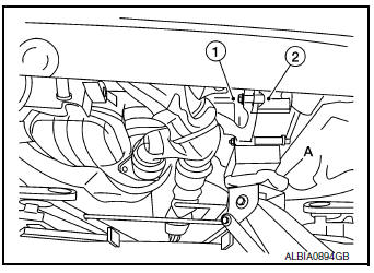
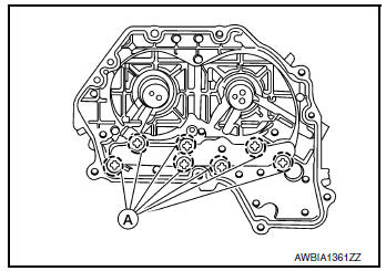
- Use a suitable jack (A) to securely support the bottom of the engine (1) and the transaxle assembly (2).
CAUTION: Put a piece of wood or an equivalent as the supporting surface and secure in a stable condition.
- Remove A/C line bracket bolt.
- Remove harness grounds from engine mounting bracket (RH).
- Remove harness retainers from engine mounting bracket (RH).
- Remove the engine mounting bracket (RH). Refer to EM-81, "Exploded View"
- Remove the RH engine mounting support bracket. Refer to EM-81, "Exploded View".
- Remove the RH engine mount torque rod. Refer to EM-81, "Exploded View".
- Disconnect harness connectors from intake valve timing intermediate lock control solenoid valve, intake valve timing control solenoid valve, and exhaust valve timing control solenoid valve connectors.
- Remove intake valve timing intermediate lock control solenoid valve, intake valve timing control solenoid valve, and exhaust valve timing control solenoid valve bolts.
- Remove intake valve timing intermediate lock control solenoid valve, intake valve timing control solenoid valve, exhaust valve timing control solenoid valve from valve timing control cover.
- . Remove O-rings from intake valve timing intermediate lock control solenoid valve, intake valve timing control solenoid valve, and exhaust valve timing control solenoid valve.
INSTALLATION
Installation is in the reverse order of removal.
CAUTION:
- Do not reuse O-rings.
- Lubricate O-rings with clean engine oil before installing.
Valve Timing Control Cover
REMOVAL
- Remove the intake valve timing intermediate lock control solenoid valve, intake valve timing control solenoid valve, exhaust valve timing control solenoid valve. Refer to EM-74, "Intake Valve Timing Intermediate Lock Control Solenoid Valve, Intake Valve Timing Control Solenoid Valve, and Exhaust Valve Timing Control Solenoid Valve".
- Remove harness grounds and retainers from the top if the engine mount bracket.
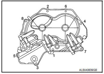
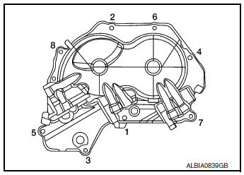
- Loosen the valve timing control cover bolts in the reverse order shown.
- Remove the valve timing control cover bolts.
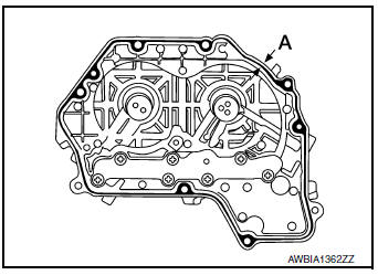
- Remove the valve timing control cover by cutting the liquid gasket using Tool (A).
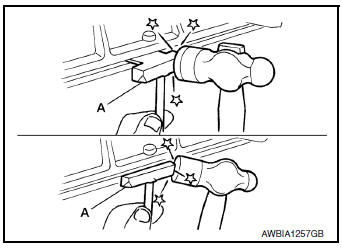
Tool number : KV10111100 (J-37228)
NOTE: Do not loosen screws (A) on the back of the valve timing control cover.
INSTALLATION
- Install valve timing control cover with the following procedure.
- Install intake valve timing intermediate lock control solenoid valve, intake valve timing control solenoid valve and exhaust valve timing control solenoid valve to valve timing control cover.
- Install O-ring to front cover side.
CAUTION: Do not reuse O-ring.
- Apply liquid gasket to the positions shown. Refer to GI-22, "Recommended Chemical Products and Sealants".
Diameter (A) : 3.4 - 4.4 mm (0.134 - 0.173 in)
- Install valve timing control cover.
- Tighten the bolts to specification in the numerical order shown.
 Camshaft
Exploded View
Camshaft position sensor (INT)
O-ring
Camshaft brackets (INT)
Camshaft brackets (EXH)
Camshaft (INT)
O-ring
Camshaft bracket (No. 1)
Camshaft sproc ...
 Oil seal
VALVE OIL SEAL
VALVE OIL SEAL : Removal and Installation
REMOVAL
Remove camshafts. Refer to EM-64, "Removal and Installation".
Remove valve lifters. Refer to EM-56, " ...
Other materials:
Component parts
Component Parts Location
Combination meter
Engine room right side
Engine room left side
No.
Component part
Description
1
Combination meter (Charge warning lamp)
The IC regulator warning function activates to illuminate the charge
warning
...
Heater operation
Heating
This mode is used to direct heated air to the foot
outlets. Some air also flows from the defrost
outlets and the side vent outlets.
Press the button to
change to fresh
air intake mode. The indicator
light
will turn off for normal heating.
Press the air flow ...
Key interlock cable
Exploded View
Key cylinder
Clip
Key interlock cable
Shift selector assembly
Removal and Installation
REMOVAL
CAUTION:
Always apply the parking brake before performing removal and installation.
Move shift selector to the “N” position.
Remo ...
