Nissan Rogue Service Manual: Symptom diagnosis
AUDIO SYSTEM
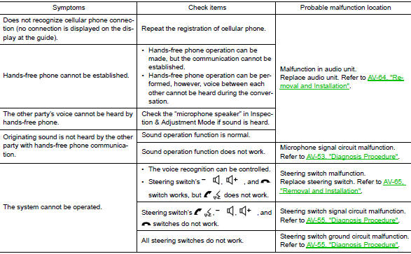
Symptom Table
RELATED TO AUDIO
|
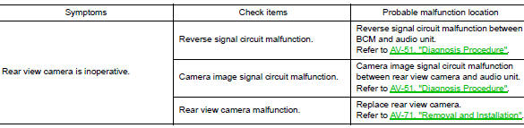
Symptoms |
Check items |
Probable malfunction location |
| The disk cannot be removed | Audio unit | Malfunction in audio unit. Refer to AV-18, "On Board Diagnosis Function". |
| No sound comes out or the level of the sound is low. | No sound from all speakers. |
|
| Only a certain speaker (front tweeter LH, front tweeter RH, front door speaker LH, front door speaker RH, rear door speaker LH, rear door speaker RH) does not output sound. |
|
|
| Noise is mixed with audio. | Noise comes out from all speakers. | Malfunction in audio unit. Refer to AV-18, "On Board Diagnosis Function". |
| Noise comes out only from a certain speaker (front tweeter LH, front tweeter RH, front door speaker LH, front door speaker RH, rear door speaker LH, rear door speaker RH). |
|
|
| Noise is mixed with radio only (when the vehicle hits a bump or while driving over bad roads) | Poor connector connection of antenna or
antenna feeder. Refer to AV-73, "Feeder Layout". |
|
| No radio reception or poor reception. |
|
|
| No satellite radio reception. | Satellite radio antenna malfunction. |
|
| Buzz/rattle sound from speaker | The majority of buzz/rattle sounds are not indicative of an issue with the speaker, usually something nearby the speaker is causing the buzz/rattle. | Refer to "SQUEAK AND RATTLE TROUBLE DIAGNOSIS" in the appropriate interior trim section. |
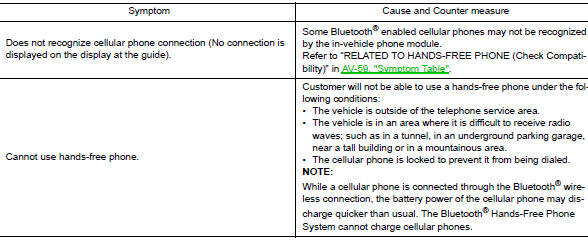
RELATED TO HANDS-FREE PHONE
- Before performing diagnosis, confirm that the cellular phone being used by the customer is compatible with the vehicle.
- It is possible that a malfunction is occurring due to a version change of the phone even though the phone is a compatible type. This can be confirmed by changing the cellular phone to another compatible type, and check that it operates normally. It is important to determine whether the cause of the malfunction is the vehicle or the cellular phone.
Check Compatibility
- Make sure the customer’s Bluetooth® related concern is understood.
- Verify the customer’s concern.
NOTE: The customer’s phone may be required, depending upon their concern.
- Write down the customer’s phone brand, model and service provider.
NOTE: It is necessary to know the service provider. On occasion, a given phone may be on the approved list with one provider, but may not be on the approved list with other providers.
- Go to “www.nissanusa.com/bluetooth/”.
- Using the website’s search engine, find out if the customer’s phone is on the approved list.
- If the customer’s phone is NOT on the approved list: Stop diagnosis here. The customer needs to obtain a Bluetooth® phone that is on the approved list before any further action.
- If the feature related to the customer’s concern shows as “N” (not compatible): Stop diagnosis here. If the customer still wants the feature to function, they will need to get an approved phone showing the feature as “Y” (compatible) in the “Basic Features”.
- If the feature related to the customer’s concern shows as “Y” (compatible): Perform diagnosis as per the following table.
RELATED TO REAR VIEW CAMERA
NORMAL OPERATING CONDITION
Description
RELATED TO NOISE
The majority of the audio concerns are the result of outside causes (bad CD, electromagnetic interference, etc.).
The following noise results from variations in field strength, such as fading noise and multi-path noise, or external noise from trains and other sources. It is not a malfunction.
- Fading noise: This noise occurs because of variations in the field strength in a narrow range due to mountains or buildings blocking the signal.
- Multi-path noise: This noise results from the waves sent directly from the broadcast station arriving at the antenna at a different time from the waves which reflect off mountains or buildings.
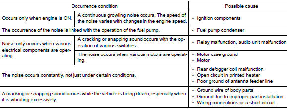
The vehicle itself can be a source of noise if noise prevention parts or electrical equipment is malfunctioning.
Check if noise is caused and/or changed by engine speed, ignition switch turned to each position, and operation of each piece of electrical equipment, and determine the cause.
NOTE: The source of the noise can be found easily by listening to the noise while removing the fuses of electrical components, one by one.
Type of Noise and Possible Cause
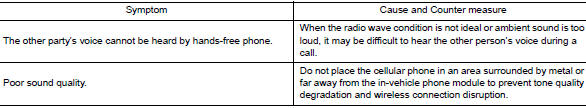
RELATED TO HANDS-FREE PHONE
 DTC/circuit diagnosis
POWER SUPPLY AND GROUND CIRCUIT
AUDIO UNIT
AUDIO UNIT : Diagnosis Procedure
Regarding Wiring Diagram information, refer to AV-27, "Wiring Diagram".
1.CHECK FUSE
Check that the following ...
 Removal and installation
AUDIO UNIT
Exploded View
Audio unit bracket (LH)
Audio unit
Audio unit bracket (RH)
Removal and Installation
REMOVAL
Disconnect the negative battery terminal. Refer ...
Other materials:
B0029 side curtain air bag module RH
DTC Logic
DTC DETECTION LOGIC
CONSULT name
DTC
DTC detecting condition
Repair order
CURTAIN AIRBAG MODULE RH CIRCUIT
[OPEN]
B0029
RH side curtain air bag module circuit
is open.
Refer to SRC-57, "Diagnosis Procedure".
CURTA ...
Ignition signal
Component Function Check
1.INSPECTION START
Turn ignition switch OFF, and restart engine.
Does the engine start?
YES-1 >> With CONSULT: GO TO 2.
YES-2 >> Without CONSULT: GO TO 3.
NO >> Proceed to EC-470, "Diagnosis Procedure".
2.CHECK IGNITION SIGNAL FUNCTIO ...
P0125 ECT sensor
DTC Description
DTC DETECTION LOGIC
DTC No.
CONSULT screen terms
(Trouble diagnosis content)
DTC detecting condition
P0125
ECT SENSOR
(Insufficient coolant temperature for closed
loop fuel control)
Voltage sent to ECM from the sensor is not practical, ...
