Nissan Rogue Service Manual: Rear window defogger and door mirror defogger do not operate
Diagnosis Procedure
Regarding Wiring Diagram information, refer to DEF-12, "Wiring Diagram".
1. CHECK REAR WINDOW DEFOGGER SWITCH
Check rear window defogger switch.
Refer to DEF-22, "WITH MANUAL A/C : Component Function Check".
Is the inspection result normal? YES >> GO TO 2.
NO >> Repair or replace the malfunctioning parts.
2. CHECK REAR WINDOW DEFOGGER RELAY
Check rear window defogger relay.
Refer to DEF-24, "Component Function Check".
Is the inspection result normal? YES >> GO TO 3.
NO >> Repair or replace the malfunctioning parts.
3. CHECK REAR WINDOW DEFOGGER POWER SUPPLY AND GROUND CIRCUIT
Check rear window defogger power supply and ground circuit.
Refer to DEF-26, "Component Function Check".
Is the inspection result normal? YES >> GO TO 4.
NO >> Repair or replace the malfunctioning parts.
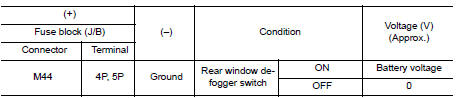
4. CHECK DOOR MIRROR DEFOGGER POWER SUPPLY
- Turn ignition switch ON.
- Check voltage between fuse block (J/B) connector and ground.
Is the inspection result normal? YES >> GO TO 5.
NO >> Replace fuse block (J/B).
5. CHECK BOTH DOOR MIRROR DEFOGGER
- Check door mirror LH. Refer to DEF-28, "Component Function Check".
- Check door mirror RH. Refer to DEF-30, "Component Function Check".
Is the inspection result normal? YES >> Check intermittent incident. Refer to GI-41, "Intermittent Incident".
NO >> Repair or replace the malfunctioning parts.
 Defogger system symptoms
Symptom Table
*:if equipped ...
 Rear window defogger does not operate but both of door mirror defogger
operate
Rear window defogger does not operate but both of door mirror defogger
operate
Diagnosis Procedure
1. CHECK REAR WINDOW DEFOGGER POWER SUPPLY AND GROUND CIRCUIT
Check rear window defogger power supply and ground circuit.
Refer to DEF-26, "Component Function Check" ...
Other materials:
Warning systems switch (if so equipped)
Warning systems switch (if so equipped)
The warning systems switch is used to turn on
and off the warning systems (Lane Departure
Warning (LDW), Forward Collision Warning
(FCW) and Blind SpotWarning (BSW) systems)
that are activated using the settings menu on the
vehicle information displa ...
Precaution
Precaution for Supplemental Restraint System (SRS) "AIR BAG" and "SEAT
BELT
PRE-TENSIONER"
The Supplemental Restraint System such as “AIR BAG” and “SEAT BELT PRE-TENSIONER”,
used along
with a front seat belt, helps to reduce the risk or severity of injury to the
...
P2014, P2016, P2017, P2018 intake manifold runner control
valve position sensor
DTC Description
DTC DETECTION LOGIC
DTC No.
CONSULT screen terms
(Trouble diagnosis content)
DTC detecting condition
P2014
IN/MANIFOLD RUNNER POS SEN B1
(Intake manifold runner position sensor/
switch circuit bank 1)
An excessively low voltage from the sensor i ...
