Nissan Rogue Service Manual: P2096, P2097 A/F sensor 1
DTC Description
DTC DETECTION LOGIC
| DTC No. | CONSULT screen terms (Trouble diagnosis content) | DTC detecting condition |
| P2096 | POST CATALYST FUEL TRIM SYS B1 (Post catalyst fuel trim system too lean bank 1) | The output voltage computed by ECM from the A/F sensor 1 signal is shifts to the lean side for a specified period. |
| P2097 | POST CATALYST FUEL TRIM SYS B1 (Post catalyst fuel trim system too rich bank 1) | The A/F signal computed by ECM from the A/F sensor 1 signal is shifts to the rich side for a specified period. |
POSSIBLE CAUSE
- A/F sensor 1
- A/F sensor 1 heater
- Heated oxygen sensor 2
- Fuel pressure
- Fuel injector
- Intake air leaks
- Exhaust gas leaks
FAIL-SAFE
Not applicable
DTC CONFIRMATION PROCEDURE
1.PRECONDITIONING
If DTC Confirmation Procedure has been previously conducted, always perform the following procedure before conducting the next test.
- Turn ignition switch OFF and wait least 10 seconds.
- Turn ignition switch ON.
- Turn ignition switch OFF and wait least 10 seconds.
TESTING CONDITION: Before performing the following procedure, confirm that battery voltage is more than 11 at idle.
>> GO TO 2.
2.PERFORM DTC CONFIRMATION PROCEDURE
- Clear the mixture ratio self-learning value. Refer to EC-143, "Work Procedure"
- Turn ignition switch OFF and wait at least 10 seconds.
- Start engine and keep the engine speed between 3,500 and 4,000 rpm for 1 minute under no load.
- Let engine idle for 1 minute.
- Keep engine speed between 2,500 and 3,000 rpm for 20 minutes.
- Check 1st trip DTC.
Is 1st trip DTC detected? YES >> Proceed to EC-426, "Diagnosis Procedure".
NO >> INSPECTION END
Diagnosis Procedure
1.CHECK HARNESS CONNECTOR
- Turn ignition switch OFF.
- Disconnect A/F sensor 1 harness connector.
- Check harness connector for water.
Water should not exit.
Is the inspection result normal? YES >> GO TO 2.
NO >> Repair or replace harness connector.
2.RETIGHTEN A/F SENSOR 1 AND HEATED OXYGEN SENSOR 2
Loosen and retighten the A/F sensor 1 and heated oxygen sensor 2. Refer to EM-29, "Exploded View", EX-5, "Exploded View".
>> GO TO 3.
3.CHECK FOR EXHAUST GAS LEAK
- Start engine and run it at idle.
- Listen for an exhaust gas leak before the three way catalyst 2.
Is exhaust gas leak detected? YES >> Repair or replace malfunctioning parts.
NO >> GO TO 4.
4.CHECK FOR INTAKE AIR LEAK
- Reconnect A/F sensor 1 harness connector.
- Start engine and run it at idle.
- Listen for an intake air leak after the mass air flow sensor.
Is intake air leak detected? YES >> Repair or replace malfunctioning parts.
NO >> GO TO 5.
5.CLEAR THE MIXTURE RATIO SELF-LEARNING VALUE
- Clear the mixture ratio self-learning value. Refer to EC-143, "Work Procedure".
- Run engine for at least 10 minutes at idle speed.
Is the 1st trip DTC P0171 or P0172 detected? Is it difficult to start engine? YES >> Perform trouble diagnosis for DTC P0171 or P0172. Refer to EC-260, "DTC Description" or EC- 265, "DTC Description".
NO >> GO TO 6.
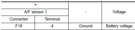
6.CHECK A/F SENSOR 1 POWER SUPPLY
- Turn ignition switch OFF.
- Disconnect A/F sensor 1 harness connector.
- Turn ignition switch ON.
- Check the voltage between A/F sensor 1 harness connector and ground.
Is the inspection result normal? YES >> GO TO 8.
NO >> GO TO 7.
7.CHECK A/F SENSOR 1 POWER SUPPLY CIRCUIT
- Turn ignition switch OFF.
- Disconnect IPDM E/R harness connector.
- Check the continuity between A/F sensor 1 harness connector and IPDM E/R harness connector.

- Also check harness for short to ground.
Is the inspection result normal? YES >> Perform the trouble diagnosis for power supply circuit.
NO >> Repair or replace error-detected parts.
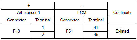
8.CHECK A/F SENSOR 1 INPUT SIGNAL CIRCUIT
- Turn ignition switch OFF.
- Disconnect ECM harness connector.
- Check the continuity between A/F sensor 1 harness connector and ECM harness connector.
- Check the continuity between A/F sensor 1 harness connector and ground, or ECM harness connector and ground.
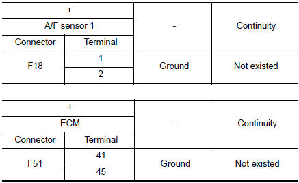
- Also check harness for short to power.
Is the inspection result normal? YES >> GO TO 9.
NO >> Repair or replace error-detected parts.
9.CHECK A/F SENSOR 1 HEATER
Check the A/F sensor 1 heater. Refer to EC-186, "Component Inspection".
Is the inspection result normal? YES >> GO TO 10.
NO >> GO TO 12.
10.CHECK HEATED OXYGEN SENSOR 2
Check heated oxygen sensor 2. Refer to EC-239, "Component Inspection".
Is the inspection result normal? YES >> GO TO 11.
NO >> Replace heated oxygen sensor 2. Refer to EX-5, "Exploded View".
11.CHECK INTERMITTENT INCIDENT
Perform GI-41, "Intermittent Incident".
Is the inspection result normal? YES >> GO TO 12.
NO >> Repair or replace error-detected parts.
12.REPLACE AIR FUEL RATIO (A/F) SENSOR 1
Replace air fuel ratio (A/F) sensor 1. Refer to EM-29, "Exploded View".
CAUTION:
- Discard any sensor which has been dropped from a height of more than 0.5 m (19.7 in) onto a hard surface such as a concrete floor; use a new one.
- Before installing new sensor, clean exhaust system threads using Oxygen Sensor Thread Cleaner [commercial service tool (J-43897-18 or J-43897-12)] and approved Anti-seize Lubricant (commercial service tool).
Do you have CONSULT? YES >> GO TO 13.
NO >> GO TO 14.
13.CONFIRM A/F ADJUSTMENT DATA
 With CONSULT
- Turn ignition switch ON.
- Select “A/F ADJ-B1” in “DATA MONITOR” mode of “ENGINE” using CONSULT.
- Make sure that “0.000” is displayed on CONSULT screen.
Is “0.000” displayed? YES >> INSPECTION END
NO >> GO TO 14.
14.CLEAR THE MIXTURE RATIO SELF-LEARNING VALUE
Clear the mixture ratio self-learning value. Refer to EC-143, "Work Procedure".
Do you have CONSULT? YES >> GO TO 15.
NO >> INSPECTION END
15.CONFIRM A/F ADJUSTMENT DATA
 With CONSULT
- Turn ignition switch ON.
- Select “A/F ADJ-B1” in “DATA MONITOR” mode of “ENGINE” using CONSULT.
- Make sure that “0.000” is displayed on CONSULT screen.
>> INSPECTION END
 P2014, P2016, P2017, P2018 intake manifold runner control
valve position sensor
P2014, P2016, P2017, P2018 intake manifold runner control
valve position sensor
DTC Description
DTC DETECTION LOGIC
DTC No.
CONSULT screen terms
(Trouble diagnosis content)
DTC detecting condition
P2014
IN/MANIFOLD RUNNER POS SEN B1
(Intake manifo ...
 P2100, P2103 throttle control motor relay
DTC Description
DTC DETECTION LOGIC
DTC No.
CONSULT screen terms
(Trouble diagnosis content)
DTC detecting condition
P2100
ETC MOT PWR-B1
(Throttle actuator ″A&# ...
Other materials:
Brake pedal vibration or operation sound occurs
Description
Brake pedal vibrates and motor sound from ABS actuator and electric unit
(control unit) occurs, when the
engine starts.
Brake pedal vibrates during braking.
CAUTION:
Vibration may be felt during brake pedal is lightly depressed (just placing a
foot on it) in the fo ...
Preparation
Special Service Tool
The actual shape of the tools may differ from those illustrated here.
Tool number
(TechMate No.)
Tool name
Description
—
(J-46534)
Trim Tool Set
Removing trim components
...
Symptom diagnosis
AUDIO SYSTEM
Symptom Table
RELATED TO AUDIO
Symptoms
Check items
Probable malfunction location
The disk cannot be removed
Audio unit
Malfunction in audio unit.
Refer to AV-18, "On Board Diagnosis Function".
No sound comes out or the le ...
