Nissan Rogue (T33) 2021-Present Service Manual: P015a A/f Sensor 1
DTC Description
DTC DETECTION LOGIC
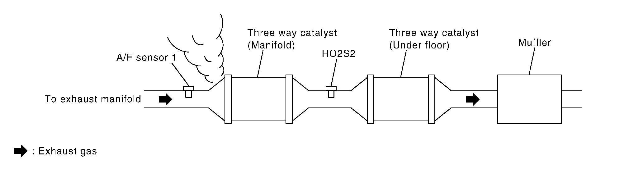
To judge malfunctions, this diagnosis measures response time of the A/F signal computed by ECM from the A/F sensor 1 signal. The time is compensated by engine operating (speed and load), fuel feedback control constant, and the A/F sensor 1 temperature index. Judgment is based on whether the compensated time (the A/F signal cycling time index) is inordinately long or not.
| DTC |
CONSULT screen terms (Trouble diagnosis content) |
DTC detection condition | ||
| P015A | 00 |
A/F SENSOR1 (B1) (O2 sensor delayed response - rich to lean bank 1 sensor 1) |
Diagnosis condition | — |
| Signal (terminal) | A/F sensor 1 signal | |||
| Threshold | The response time of a A/F sensor 1 signal delays more than the specified time computed by ECM | |||
| Diagnosis delay time | — | |||
POSSIBLE CAUSE
-
Harness or connectors (The A/F sensor 1 circuit is open or shorted.)
-
A/F sensor 1
FAIL-SAFE
Not applicable
DTC Confirmation Procedure
PRECONDITIONING
If DTC Confirmation Procedure has been previously conducted, always perform the following procedure before conducting the next test.
-
Turn ignition switch OFF and wait at least 10 seconds.
-
Turn ignition switch ON.
-
Turn ignition switch OFF and wait at least 10 seconds.
TESTING CONDITION:
Before performing the following procedure, confirm that battery voltage is more than 11 V at idle.
Do you have CONSULT?
YES>>GO TO 2.
NO>>GO TO 6.
PERFORM DTC CONFIRMATION PROCEDURE-1
 With CONSULT
-
Start engine and warm it up to normal operating temperature.
-
Turn ignition switch OFF and wait at least 10 seconds.
-
Turn ignition switch ON.
-
Turn ignition switch OFF and wait at least 10 seconds.
-
Start engine and keep the engine speed between 3,500 and 4,000 rpm for at least 1minute under no load.
-
Let engine idle for 1 minute.
-
Increase the engine speed up to about 3,600 rpm and keep it for 10 seconds.
-
Fully release accelerator pedal and then let engine idle for about 1 minute.
-
Check the items status of “DATA MONITOR” as follows.
 NOTE:
NOTE:
If “PRSNT” changed to “ABSNT”, refer to Component Function Check.
Data monitor item Status A/F SEN1 DIAG3 (B1) PRSNT
Is “PRSNT” displayed on CONSULT screen?
YES>>GO TO 4.
NO>>GO TO 3.
PERFORM DTC CONFIRMATION PROCEDURE-2
With CONSULT
Perform DTC confirmation procedure-1 again.
Is “PRSNT” displayed on CONSULT screen?
YES>>GO TO 4.
NO>>Refer to Component Function Check.
PERFORM DTC CONFIRMATION PROCEDURE-2
With CONSULT
-
Wait for about 20 seconds at idle.
-
Check the items status of “DATA MONITOR” as follows.
NOTE:
If “CMPLT” changed to “INCMP”, refer to Component Function Check.
Data monitor item Status A/F SEN1 DIAG1 (B1) CMPLT A/F SEN1 DIAG2 (B1)
Is “CMPLT” displayed on CONSULT screen?
YES>>GO TO 5.
NO>>Refer to Component Function Check.
PERFORM SELF-DIAGNOSIS
With CONSULT
Check the “SELF-DIAG RESULT”.
Is any DTC detected?
YES>>Proceed to DTC Diagnosis Procedure.
NO>>INSPECTION END
CHECK AIR-FUEL RATIO SELF-LEARNING VALUE
 With GST
-
Start engine and warm it up to normal operating temperature.
-
Select Service $01 with GST.
-
Calculate the total value of “Short term fuel trim” and “Long term fuel trim” indications.
Is the total percentage within ±15%?
YES>>GO TO 8.
NO>>GO TO 7.
DETECT MALFUNCTIONING PART
Check the following.
-
Intake air leaks
-
Exhaust gas leaks
-
Incorrect fuel pressure
-
Lack of fuel
-
Fuel injector
-
Incorrect PCV hose connection
-
PCV valve
-
Mass air flow sensor
>>
Repair or replace malfunctioning part.
PERFORM DTC CONFIRMATION PROCEDURE
-
Turn ignition switch OFF and wait at least 10 seconds.
-
Turn ignition switch ON.
-
Turn ignition switch OFF and wait at least 10 seconds.
-
Start engine and keep the engine speed between 3,500 and 4,000 rpm for at least 1 minute under no load.
-
Let engine idle for 1 minute.
-
Increase the engine speed up to about 3,600 rpm and keep it for 10 seconds.
-
Fully release accelerator pedal and then let engine idle for about 1 minute.
-
Check 1st trip DTC.
Is 1st trip DTC detected?
YES>>Proceed to DTC Diagnosis Procedure.
NO-1>>To check malfunction symptom before repair: Refer to Intermittent Incident.
NO-2>>Confirmation after repair: INSPECTION END
DTC Diagnosis Procedure
RETIGHTEN A/F SENSOR 1
Loosen and retighten the A/F sensor 1. Refer to Exploded View.
>>
GO TO 2.
CHECK EXHAUST GAS LEAK
-
Start engine and run it at idle.
-
Listen for an exhaust gas leak before three way catalyst (manifold).
Is exhaust gas leak detected?
YES>>Repair or replace.
NO>>GO TO 3.
CHECK FOR INTAKE AIR LEAK
Listen for an intake air leak after the mass air flow sensor.
Is intake air leak detected?
YES>>Repair or replace.
NO>>GO TO 4.
CLEAR THE MIXTURE RATIO SELF-LEARNING VALUE
-
Clear the mixture ratio self-learning value. Refer to Description.
-
Run engine for at least 10 minutes at idle speed.
Is the 1st trip DTC P0171 or P172 detected? Is it difficult to start engine?
YES>>Perform trouble diagnosis for DTC P0171 or P0172. Refer to DTC Description or DTC Description.
NO>>GO TO 5.
CHECK AIR FUEL RATIO (A/F) SENSOR 1 POWER SUPPLY CIRCUIT
-
Disconnect A/F sensor 1 harness connector.
-
Turn ignition switch ON.
-
Check the voltage between A/F sensor 1 harness connector and ground.
+ – Voltage A/F sensor 1 Connector Terminal F18 4 Ground Battery voltage
Is the inspection result normal?
YES>>GO TO 6.
NO>>Repair or replace error-detected parts.
CHECK A/F SENSOR 1 INPUT SIGNAL CIRCUIT
-
Turn ignition switch OFF.
-
Disconnect ECM harness connector.
-
Check the continuity between A/F sensor 1 harness connector and ECM harness connector.
+ – Continuity A/F sensor 1 ECM Connector Terminal Connector Terminal F18 1 F72 56 Existed 2 60 -
Check the continuity between A/F sensor 1 harness connector and ground, or ECM harness connector and ground.
+ – Continuity A/F sensor 1 Connector Terminal F18 1 Ground Not existed 2 + – Continuity ECM Connector Terminal F72 56 Ground Not existed 60 -
Also check harness for short to power.
Is the inspection result normal?
YES>>GO TO 7.
NO>>Repair or replace error-detected parts.
CHECK AIR FUEL RATIO (A/F) SENSOR 1 HEATER
Refer to Component Inspection.
Is the inspection result normal?
YES>>GO TO 8.
NO>>GO TO 11.
CHECK MASS AIR FLOW SENSOR
Refer to Component Inspection.
Is the inspection result normal?
YES>>GO TO 9.
NO>>Replace mass air flow sensor. Refer to Exploded View.
CHECK PCV VALVE
Refer to POSITIVE CRANKCASE VENTILATION : Periodic Maintenance.
Is the inspection result normal?
YES>>GO TO 10.
NO>>Repair or replace PCV valve. Refer to Exploded View.
CHECK INTERMITTENT INCIDENT
Refer to Intermittent Incident.
Is the inspection result normal?
YES>>GO TO 11.
NO>>Repair or replace.
REPLACE AIR FUEL RATIO (A/F) SENSOR 1
Replace air fuel ratio (A/F) sensor 1. Refer to Exploded View.
>>
INSPECTION END
Other materials:
Dtc/circuit Diagnosis. B0028-1a Side A/b Module Rh
DTC Description
DTC DETECTION LOGIC DTC No.
CONSULT screen items
(Trouble diagnosis content) DTC Detection Condition
B0028-1A
SIDE A/B MODULE RH
(Right Side Airbag Deployment Control)
Diagnosis condition
When ignition switch is ON.
Signal (terminal)
Front side air bag modu ...
Dtc/circuit Diagnosis. B1029-09 Front Seat Belt Pre-Tensioner Lh
DTC Description
DTC DETECTION LOGIC DTC No.
CONSULT screen items
(Trouble diagnosis content) DTC Detection Condition
B1029-09
Front seat belt pre-tensioner LH
(Front seat belt pre-tensioner left hand)
Diagnosis condition
When ignition switch is ON.
Signal (terminal)
Front ...
Dtc/circuit Diagnosis. C161b-86 Abs System
DTC Description
DTC DETECTION LOGIC DTC No.
CONSULT screen terms
(Trouble diagnosis content) DTC detection condition
C161B
86
ABS system
(Anti-lock braking system )
Diagnosis condition
When ignition switch is ON.
Signal (terminal)
CAN communication signal
Threshold ...