Nissan Rogue Service Manual: Oil pump
Exploded View
- Front cover (Oil pump body united)
- Outer rotor
- Inner rotor
- Oil pump cover
- Regulator valve
- Regulator valve spring
- Regulator valve plug
CAUTION: Before assembly, apply new engine oil to the parts as shown above.
Removal and Installation
REMOVAL
Remove front cover. Refer to EM-44, "Exploded View".
NOTE: Oil pump is built into front cover.
INSTALLATION
Installation is in the reverse order of removal.
- When installing, align crankshaft flat faces with inner rotor flat faces.
Disassembly and Assembly
DISASSEMBLY
- Remove bolts and oil pump cover.
- Remove inner rotor and outer rotor from front cover.
- After removing regulator valve plug, remove regulator valve spring and regulator valve.
ASSEMBLY
Assembly is in the reverse order of disassembly.
- Install the inner rotor and outer rotor with the punched marks on the oil pump cover side.
CAUTION: Before assembly apply new engine oil to the parts specified.
Inspection
INSPECTION AFTER DISASSEMBLY
OIL PUMP CLEARANCE
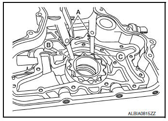
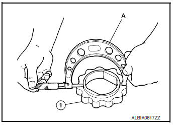
- Measure the clearance using a suitable tool (A).
- Clearance between outer rotor (B) and front cover (C)
Standard : Refer to LU-17, "Oil Pump".
- Tip clearance between inner rotor and outer rotor (B)
Standard : Refer to LU-17, "Oil Pump".
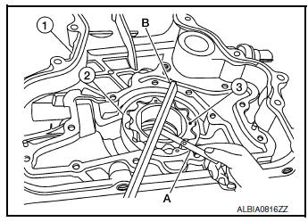
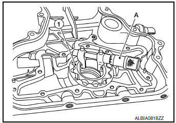
- Measure the clearance using suitable tools (A/B).
- Side clearance between inner rotor (3) and front cover (1)
Standard : Refer to LU-17, "Oil Pump".
- Side clearance between outer rotor (2) and front cover (1)
Standard : Refer to LU-17, "Oil Pump".
- Calculate the clearance between oil pump inner rotor and oil pump body as follows:
- Measure the outer diameter of protruded portion of inner rotor (1) using a suitable tool (A).
- Measure the inner diameter of inner rotor (1) using a suitable tool (A).
- (Clearance) = (Inner rotor inner diameter) – (Oil pump inner rotor outer diameter)
Standard : Refer to LU-17, "Oil Pump".
- If measured/calculated values are out of the standard, replace front cover and oil pump assembly.
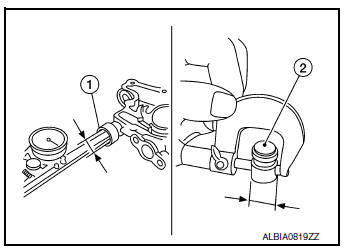
REGULATOR VALVE TO OIL PUMP COVER CLEARANCE
- (Clearance) = (Regulator valve hole (1) diameter) – (Regulator valve (2) outer diameter)
Standard : Refer to LU-17, "Oil Pump".
- If the calculated value is out of the standard, replace front cover and oil pump assembly.
CAUTION:
- Coat regulator valve with engine oil.
- Make sure that it falls smoothly into valve hole by its own weight.
INSPECTION AFTER INSTALLATION
- Before starting engine, check oil/fluid levels including engine coolant and engine oil. If less than required quantity, fill to the specified level. Refer to MA-11, "Fluids and Lubricants".
- Use procedure below to check for fuel leaks.
- Turn ignition switch ON (with engine stopped). With fuel pressure applied to fuel piping, check for fuel leaks at connection points.
- Start engine. With engine speed increased, check again for fuel leaks at connection points.
- Run engine to check for unusual noise and vibration.
NOTE: If hydraulic pressure inside timing chain tensioner drops after removal and installation, slack in the guide may generate a pounding noise during and just after engine start. However, this is normal. Noise will stop after hydraulic pressure rises.
- Warm up engine thoroughly to make sure there are no leaks of fuel, exhaust gas, or any oils/fluids including engine oil and engine coolant.
- Bleed air from passages in lines and hoses, such as in cooling system.
- After cooling down engine, again check oil/fluid levels including engine oil and engine coolant. Refill to specified level, if necessary.
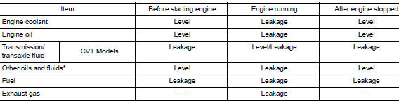
- Summary of the inspection items:
*Power steering fluid, brake fluid, etc.
 Oil cooler
Exploded View
Intake manifold
Cylinder block
Clamp
Water hose
Water hose clip
Water hose
Oil cooler
Gasket
Oil cooler relief val ...
 Service data and specifications (SDS)
Oil Pressure
*: Engine oil temperature at 80°C (176°F)
Oil Pump
Relief Valve
Oil Capacity
...
Other materials:
Basic inspection
DIAGNOSIS AND REPAIR WORKFLOW
Work Flow
OVERALL SEQUENCE
DETAILED FLOW
1.GET INFORMATION FOR SYMPTOM
Get detailed information from the customer about the symptom (the
condition and the environment when
the incident/malfunction occurs).
Check operation condition of the ...
Power supply and ground circuit
BCM (BODY CONTROL SYSTEM) (WITH INTELLIGENT KEY SYSTEM)
BCM (BODY CONTROL SYSTEM) (WITH INTELLIGENT KEY SYSTEM) : Diagnosis
Procedure
Regarding Wiring Diagram information, refer to BCS-50, "Wiring Diagram".
1. CHECK FUSE
Check that the following fuse is not blown.
Is the fuse blown ...
Component parts
Component Parts Location
View of cowl area (with cowl top cover
removed)
RH front of vehicle (with front
bumper fascia removed)
View with back door finisher removed
No.
Component
Function
1
Combination switch
(Wiper and washer switch)
Ref ...
