Nissan Rogue Service Manual: Key switch signal circuit (without intelligent key)
Description
Transmits a key switch signal to the BCM.
Component Function Check
1. CHECK BCM INPUT SIGNAL
Select "Data Monitor" for "BCM" and check the "KEY ON SW" monitor value.
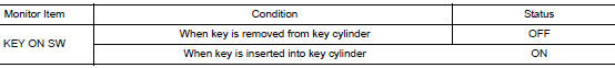
Is the inspection result normal? YES >> Inspection End.
NO >> Refer to WCS-47, "Diagnosis Procedure".
Diagnosis Procedure
Regarding Wiring Diagram information, refer to WCS-29, "Wiring Diagram".
1. CHECK BCM INPUT SIGNAL
Check voltage between BCM harness connector M19 terminal 81 and ground.
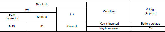
Is the inspection result normal? YES >> Inspection End.
NO >> GO TO 2.
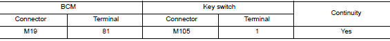
2. CHECK KEY SWITCH CIRCUIT
- Disconnect BCM connector M19 and key switch.
- Check continuity between BCM harness connector M19 terminal 81 and key switch harness connector M105 terminal 1.
- Check continuity between BCM harness connector M19 terminal 81 and ground.
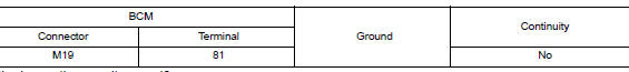
Is the inspection result normal? YES >> GO TO 3.
NO >> Repair or replace harness or connector.
3. CHECK KEY SWITCH POWER SUPPLY CIRCUIT
Check voltage between key switch harness connector M105 terminal 1 and ground.
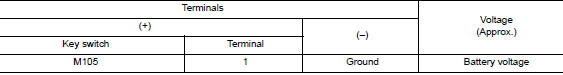
Is the inspection result normal? YES >> GO TO 4.
NO >> Repair or replace harness or connector.
4. CHECK KEY SWITCH GROUND CIRCUIT
Check continuity between key switch harness connector M105 terminal 2 and ground.
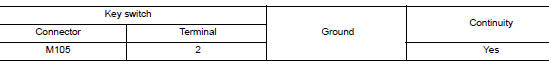
Is the inspection result normal? YES >> Replace key switch.
NO >> Repair or replace harness or connector.
Component Inspection
1. CHECK KEY SWITCH
- Turn ignition switch OFF.
- Disconnect key switch.
- Check continuity between key switch terminals 1 and 2.
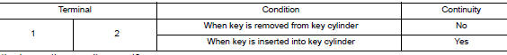
Is the inspection result normal? YES >> Inspection End.
NO >> Replace key switch.
 Parking brake switch signal circuit
Component Function Check
1.CHECK PARKING BRAKE SWITCH OPERATION
Check that brake warning lamp in combination meter turns ON/OFF when parking
brake is actuated.
Is the inspection result normal?
...

Other materials:
DTC/circuit diagnosis
POWER SUPPLY AND GROUND CIRCUIT
BCM (BODY CONTROL SYSTEM) (WITH INTELLIGENT KEY SYSTEM)
BCM (BODY CONTROL SYSTEM) (WITH INTELLIGENT KEY SYSTEM) : Diagnosis
Procedure
Regarding Wiring Diagram information, refer to BCS-50, "Wiring Diagram".
1. CHECK FUSE
Check that the following fuse i ...
Connecting procedure
NOTE:
The connecting procedure must be performed
when the vehicle is stationary. If the
vehicle starts moving during the procedure,
the procedure will be cancelled.
To connect a phone to the Bluetooth® Hands-
Free Phone System:
Press the SETTING button.
Use the TUNE/FOLDER or TUNE ...
Supplemental air bag warning light
The supplemental air bag warning light,
displaying in the instrument panel,
monitors
the circuits for the air bag systems, pretensioners
and all related wiring.
When the ignition switch is placed in the ON
position, the supplemental air bag warning light
illuminates for about 7 second ...
