Nissan Rogue Owners Manual: Instrument panel
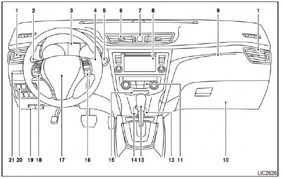
- Vent
- Headlight/fog light (if so equipped)/turn signal switch
- Meters, gauges, warning/indicator lights and Vehicle Information Display
- Windshield wiper/washer switch and rear window wiper/washer switch /Ignition switch (if so equipped)
- Push-button ignition switch (if so equipped)
- Vent
- Hazard warning flasher switch
- Radio /Navigation system* (if so equipped)
- . Front passenger supplemental air bag
- Glove box
- Heater and air conditioning controls
- Power outlet
- Shift lever
- Auxiliary jack /USB port
- Front passenger air bag status light
- Cruise control main/set switches (/Bluetooth Hands-Free Phone System (if so equipped)
- Driver supplemental air bag/Horn (, )
- Control panel and Vehicle Information Display switches
- Hood release /Fuel door release
- Vehicle Dynamic Control (VDC) OFF switch Sport mode switch ECO mode switch (if so equipped) Power liftgate switch (if so equipped) (P.3-28) Power liftgate main switch (if so equipped) Warning systems switch (if so equipped) All-Wheel Drive (AWD) lock switch (if so equipped) Hill descent control switch (if so equipped)
- Instrument brightness control /Twin trip odometer reset switch
*: Refer to the separate Navigation System Owner’s Manual (if so equipped).
Refer to the page number indicated in parentheses for operating details.

 Meters and gauges
Tachometer
Warning/indicator lights
Vehicle Information Display/Odometer/
Twin trip odometer
Speedometer
Fuel gauge
Engine coolant temperature gauge
...
Other materials:
P2135 TP sensor
DTC Description
DTC DETECTION LOGIC
DTC No.
CONSULT screen terms
(Trouble diagnosis content)
DTC detecting condition
P2135
TP SENSOR-B1
(Throttle/pedal position sensor/switch ″A″ /
″B″ voltage correlation)
Rationally incorrect voltage is ...
Seat belt warning system
Seat Belt Warning System Does Not Function
1.SEAT BELT WARNING LIGHT
Turn ignition switch ON.
Does the seat belt warning lamp come ON?
YES >> GO TO 2.
NO >>
Check 10A fuse [No. 13, located in the fuse block (J/B)].
Check seat belt buckle switch (driver seat).
...
Preparation
Special Service Tool
The actual shape of the tools may differ from those illustrated here.
Tool number
(TechMate No.)
Tool name
Description
KV991J0070
(J-45695-A)
Coolant refill tool
Refilling engine cooling system
Commercial Service Too
...
