Nissan Rogue Service Manual: Input speed sensor
Exploded View
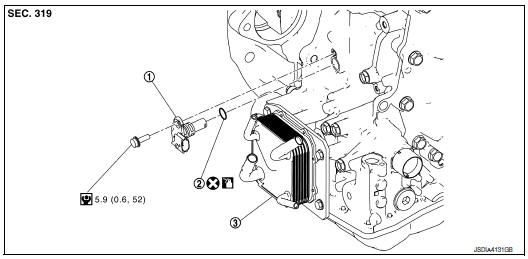
- Input speed sensor
- O-ring
- Transaxle assembly
 : Always replace after every
disassembly.
: Always replace after every
disassembly.
 : N·m (kg-m, in-lb)
 : Apply CVT fluid
Removal and Installation
REMOVAL
- Remove battery tray. Refer to TM-207, "Removal and Installation".
- Remove the starter motor. Refer to STR-21, "Removal and Installation".
- Disconnect the input speed sensor harness connector.
- Remove the input speed sensor bolt and remove the input speed sensor.
- Remove the O-ring from the input speed sensor.
INSTALLATION
Installation is in the reverse order of removal.
CAUTION:
- Do not reuse O-ring.
- Apply CVT fluid to the O-ring.
Inspection and Adjustment
INSPECTION AFTER INSTALLATION
Check for CVT fluid leakage. Refer to TM-190, "Inspection".
ADJUSTMENT AFTER INSTALLATION
Adjust the CVT fluid level. Refer to TM-192, "Adjustment".
 Oil pan
Exploded View
COMPONENT PARTS LOCATION
Transaxle assembly
Oil pan gasket
Oil pan
Drain plug
Drain plug gasket
Magnet
Overflow plug
O-ring
Always replace after every
d ...
 Primary speed sensor
Exploded View
Transaxle assembly
O-ring
Primary speed sensor
: Always replace after every
disassembly.
: N·m (kg-m, in-lb)
: Apply CVT fluid
Removal and Installation
REMOVAL
...
Other materials:
Rear window and outside mirror (if so equipped) defroster switch
To defrost the rear window glass and outside
mirrors (if so equipped), start the engine and
push the rear window defroster switch on. The
rear window defroster indicator light on the
switch comes on. Push the switch again to turn
the defroster off.
The rear window defroster automatically ...
The low washer fluid warning continues displaying, or
does not display
Description
The warning is still displayed even after washer fluid is added.
The warning is not displayed even though the washer tank is empty.
Diagnosis Procedure
1.CHECK WASHER FLUID LEVEL SWITCH SIGNAL CIRCUIT
Check the washer fluid level switch signal circuit. Refer to MWI-71,
" ...
DTC/circuit diagnosis
U1000 CAN COMM CIRCUIT
Description
Refer to LAN-8, "System Description".
DTC Logic
DTC DETECTION LOGIC
NOTE:
U1000 can be set if a module harness was disconnected and reconnected, perhaps
during a repair. Confirm
that there are actual CAN diagnostic symptoms and a present DTC by p ...
