Nissan Rogue Service Manual: Harness
Harness Layout
HOW TO READ HARNESS LAYOUT
The following Harness Layouts use a map style grid to help locate connectors on the drawings:
- Main Harness and Main Sub Harness
- Engine Room Harness
- Engine Room Harness (Passenger Compartment)
- Front End Module Harness
- Engine Control Harness
- Body Harness
- Body No. 2 Harness
- Room Lamp Harness
To use the grid reference
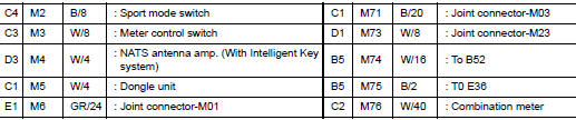
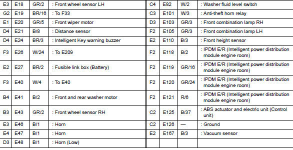
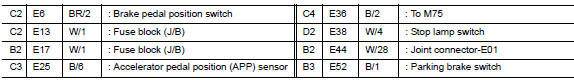
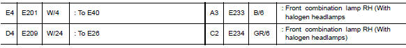
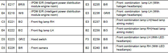
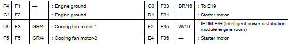
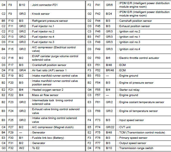
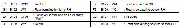
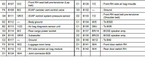
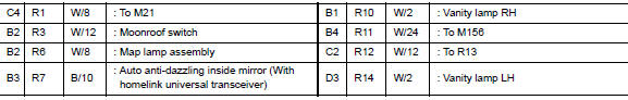
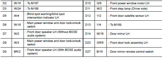
- Find the desired connector number on the connector list.
- Find the grid reference.
- On the drawing, find the crossing of the grid reference letter column and number row.
- Find the connector number in the crossing zone.
- Follow the line (if used) to the connector.
OUTLINE
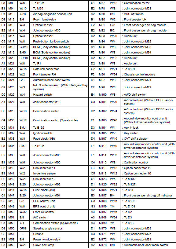
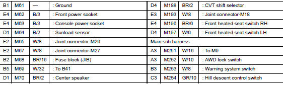
MAIN HARNESS
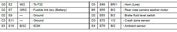
ENGINE ROOM HARNESS
ENGINE ROOM HARNESS (PASSENGER COMPARTMENT)

FRONT END MODULE HARNESS
ENGINE CONTROL HARNESS
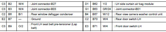
BODY HARNESS
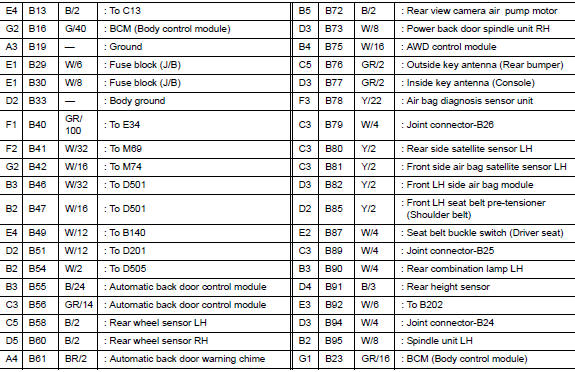
BODY NO. 2 HARNESS
ROOM LAMP HARNESS

FRONT DOOR LH HARNESS
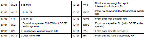
FRONT DOOR RH HARNESS
REAR DOOR LH HARNESS
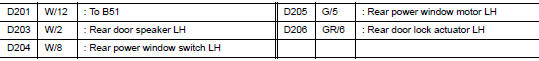
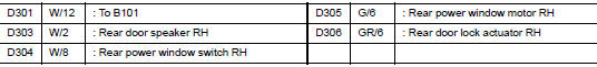
REAR DOOR RH HARNESS
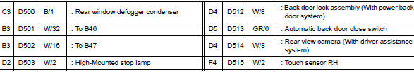
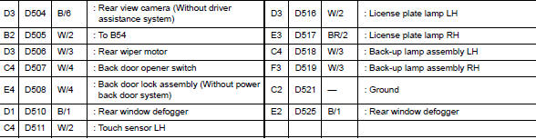
BACK DOOR HARNESS
 Ground
Ground Distribution
MAIN HARNESS
ENGINE ROOM HARNESS
ENGINE CONTROL HARNESS
BODY HARNESS
BODY NO. 2 HARNESS
...
 Electrical units location
Electrical Units Location
ENGINE COMPARTMENT
PASSENGER COMPARTMENT
...
Other materials:
Preparation
Special Service Tool
The actual shape of the tools may differ from those illustrated here.
Tool number
(TechMate No.)
Tool name
Description
—
(J-46534)
Trim Tool Set
Removing trim components
...
Fender protector
FENDER PROTECTOR
FENDER PROTECTOR : Exploded View
Front fender protector
Engine side cover
Front fender
Over fender
Clip
Front
FENDER PROTECTOR : Removal and Installation
REMOVAL
Remove wheel and tire using power tool. Refer to WT-60, "Removal and
Install ...
Front seat
DRIVER SIDE
DRIVER SIDE : Exploded View
POWER SEAT
Headrest
Seatback support
Seatback board
Seatback heater (if equipped)
Seatback trim
Seatback pad
Seat cushion outer finisher (RH)
Seat cushion rear finisher
(RH)
Seat cushion inner fini ...
