Nissan Rogue Service Manual: Front door finisher
Exploded View
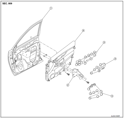
- Front door
- Front door pull handle bracket
- Front door pull handle
- Front power window switch (RH) finisher
- Front door inside handle finisher
- Front door finisher
 Clip
Clip
 Pawl
Pawl
REMOVAL
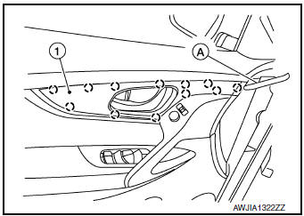
NOTE: LH shown, RH similar.
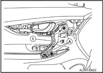
- Release pawls using a suitable tool (A) from front of inside handle finisher (1) while working toward the rear and remove.
: Pawl
- Release pawls using a suitable tool (A) from front of inside handle finisher (1) while working toward the rear and remove.
: Pawl
- Disconnect harness connector from door mirror remote control switch (LH only).
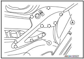
- Remove bolts (A) and front door inside pull handle bracket (1).
- Release pawls using a suitable tool (A) and remove front door power window and door lock/unlock switch finisher (1).
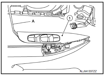
- Disconnect harness connectors from front door power window and door lock/unlock switch.
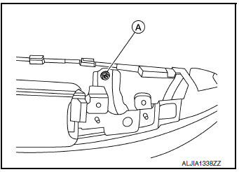
- Remove front door finisher bolt (A).
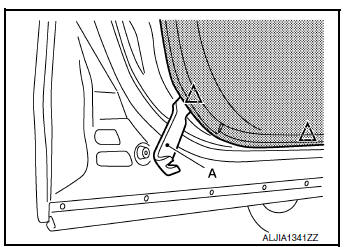
- Insert suitable tool (A) between front door finisher and door panel to release clips and pawl, starting from the bottom and working to the top.
 : Clip
INSTALLATION
Installation is in the reverse order of removal.
CAUTION:
- Visually check the clips and pawls for deformation and damage during installation. Replace with new ones if necessary.
- When installing front door finisher, check that clips and pawls are securely placed in door panel holes.
NOTE: When main power window and door lock/unlock switch or power window door lock/unlock switch RH is removed or replaced, it is necessary to perform the initialization procedure. Refer to PWC-25, "Work Flow".

 Rear door finisher
Exploded View
Rear door
Rear power window switch finisher
Rear door screw cover
Rear door inside handle finisher
Rear door finisher
Tether clip
Tether ...
Other materials:
Symptom diagnosis
INTERIOR LIGHTING SYSTEM SYMPTOMS
Symptom Table
CAUTION:
Perform the self-diagnosis with CONSULT before the symptom diagnosis. Perform
the trouble diagnosis
if any DTC is detected.
Symptom
Possible cause
Inspection item
All the following lamps do not turn ON. ...
Precaution
Precaution for Supplemental Restraint System (SRS) "AIR BAG" and "SEAT
BELT
PRE-TENSIONER"
The Supplemental Restraint System such as “AIR BAG” and “SEAT BELT
PRE-TENSIONER”, used along
with a front seat belt, helps to reduce the risk or severity of injury to the
...
Structure and operation
Positive Crankcase Ventilation
This system returns blow-by gas to the intake manifold.
The positive crankcase ventilation (PCV) valve is provided to conduct crankcase
blow-by gas to the intake
manifold.
During partial throttle operation of the engine, the intake manifold sucks the
bl ...
