Nissan Rogue Service Manual: ECU diagnosis information
BCM
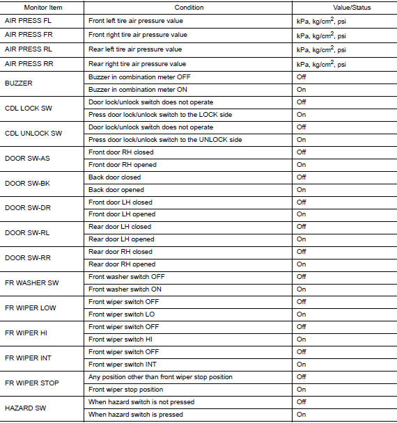
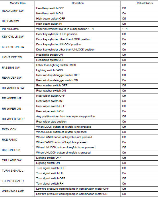
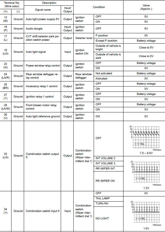
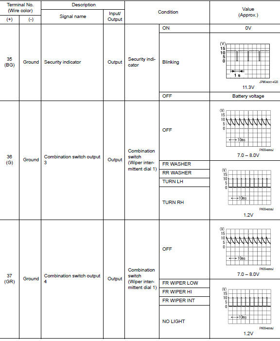
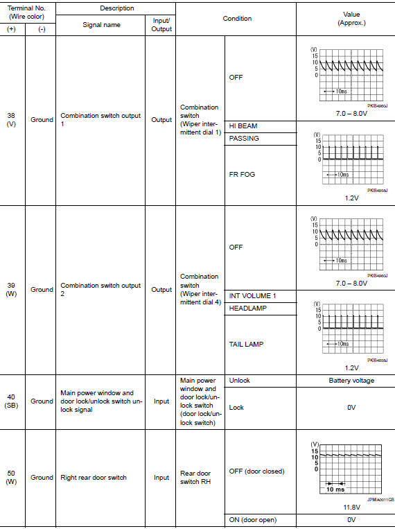
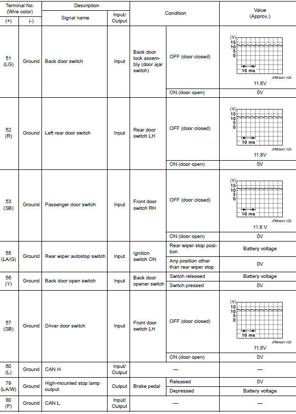
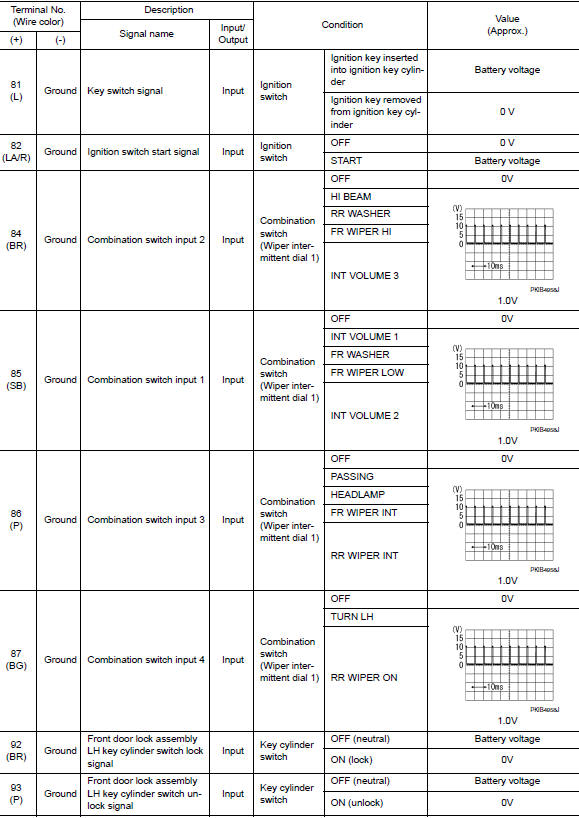
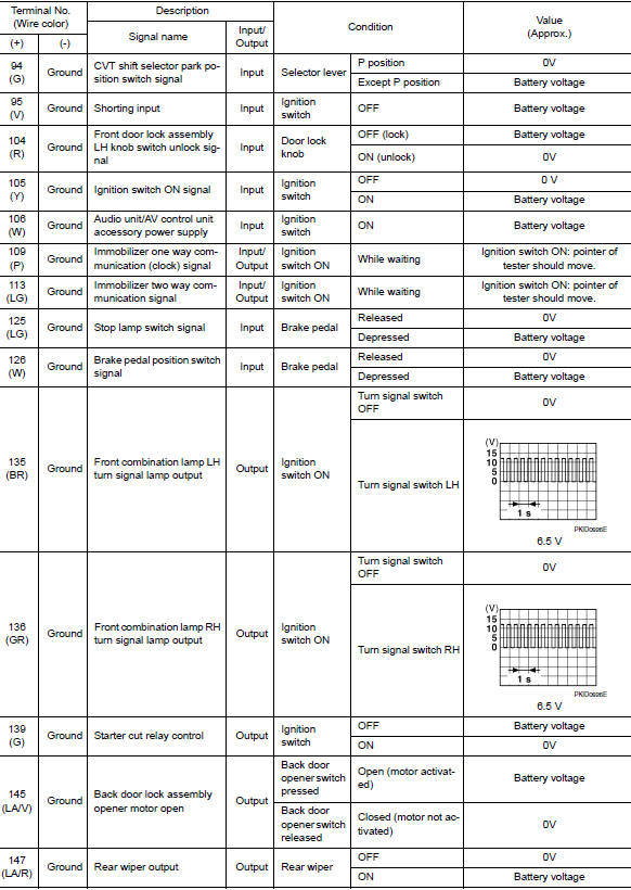
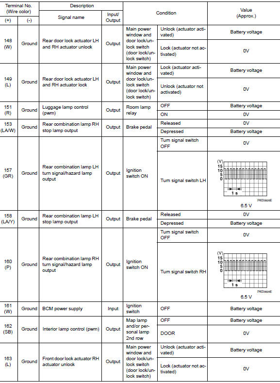
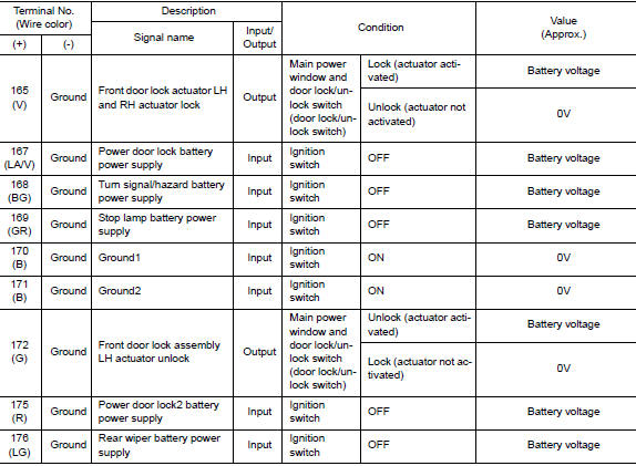
Reference Value
NOTE: The Signal Tech II Tool (J-50190) can be used to perform the following functions. Refer to the Signal Tech II User Guide for additional information.
- Activate and display TPMS sensor IDs
- Display tire pressure reported by the TPMS sensor
- Read TPMS DTCs
- Register TPMS sensor IDs
VALUES ON THE DIAGNOSIS TOOL
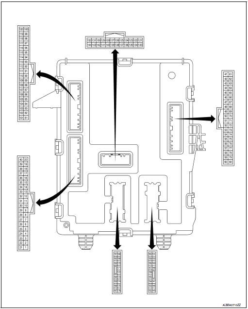
TERMINAL LAYOUT
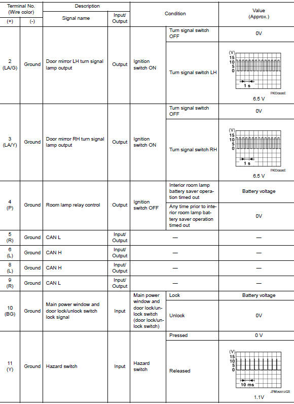
PHYSICAL VALUES
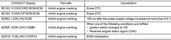
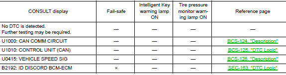
Fail Safe
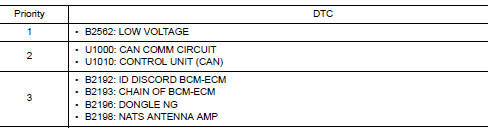
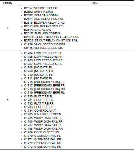
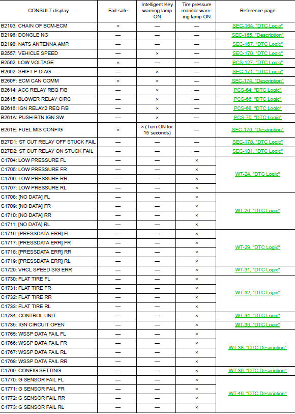
DTC Inspection Priority Chart
If some DTCs are displayed at the same time, perform inspections one by one based on the following priority chart.
DTC Index
NOTE: Details of time display
- CRNT: Displays when there is a malfunction now or after returning to the normal condition until turning ignition switch OFF → ON again.
- 1 - 39: Displayed if any previous malfunction is present when current condition is normal. It increases like 1 → 2 → 3...38 → 39 after returning to the normal condition whenever ignition switch OFF → ON. The counter remains at 39 even if the number of cycles exceeds it. It is counted from 1 again when turning ignition switch OFF → ON after returning to the normal condition if the malfunction is detected again.
 System description
COMPONENT PARTS
BODY CONTROL SYSTEM
BODY CONTROL SYSTEM : Component Parts Location
BCM
Behind instrument panel (LH)
POWER CONSUMPTION CONTROL SYSTEM
POWER CONSUMPTION CONTROL SYSTEM : ...
 Wiring diagram
BCM
Wiring Diagram
...
Other materials:
Steering column
Inspection
HOLE COVER SEAL, HOLE COVER AND LOWER SHAFT
Check each part of hole cover seal, hole cover and steering column and lower
shaft for damage or other malfunctions.
Replace if necessary.
STEERING COLUMN
Check each part of steering column for damage or other
malfunctions. ...
P1225 TP sensor
DTC Description
DTC DETECTION
DTC No.
CONSULT screen terms
(Trouble diagnosis content)
DTC detecting condition
P1225
CTP LEARNING-B1
(CTP LEARNING-B1)
Closed throttle position learning value is excessively low.
POSSIBLE CAUSE
Electric throttle control actua ...
Brake pedal
Exploded View
Rivet
Clevis pin
Brake pedal
Brake pedal pad
Clip
Snap pin
Stop lamp switch
Brake pedal position switch
Removal and Installation
REMOVAL
Remove instrument lower panel LH. Refer to IP-22, "Removal and
Installation". ...
