Nissan Rogue Service Manual: DTC/Circuit diagnosis
C1201 AWD CONTROL UNIT
DTC Description
DTC DETECTION LOGIC
| DTC No. | CONSULT screen terms (Trouble diagnosis content) | DTC detecting condition |
| C1201 | CONTROLLER FAILURE (Control unit failure) | Malfunction has occurred inside AWD control unit. |
POSSIBLE CAUSE
Internal malfunction of AWD control unit
FAIL-SAFE
AWD control changes to front-wheel drive immediately, then AWD control stops, and the vehicle becomes front-wheel drive.
DTC CONFIRMATION PROCEDURE
1.PRECONDITIONING
If “DTC CONFIRMATION PROCEDURE” has been previously conducted, always turn ignition switch OFF and wait at least 10 seconds before conducting the next test.
>> GO TO 2.
2.DTC REPRODUCTION PROCEDURE
 With CONSULT
- Turn the ignition switch OFF to ON.
- Perform self-diagnosis for “ALL MODE AWD/4WD”.
Is DTC “C1201” detected? YES >> Proceed to diagnosis procedure. Refer to DLN-36, "Diagnosis Procedure".
NO-1 >> To check malfunction symptom before repair: Refer to GI-41, "Intermittent Incident".
NO-2 >> Confirmation after repair: INSPECTION END
Diagnosis Procedure
1.PERFORM SELF-DIAGNOSIS
 With CONSULT
- Erase self-diagnostic results for “ALL MODE AWD/4WD”.
- Turn the ignition switch OFF, and then wait 10 seconds or more.
- Perform self-diagnosis for “ALL MODE AWD/4WD”.
Is DTC “C1201” detected? YES >> Replace AWD control unit. Refer to DLN-67, "Removal and Installation".
NO >> Check AWD control unit pin terminals for damage or loose connection with harness connector. If any items are damaged, repair or replace error-detected parts.
C1203 ABS ACTUATOR AND ELECTRIC UNIT (CONTROL UNIT)
DTC Description
DTC DETECTION LOGIC
| DTC No. | CONSULT screen terms (Trouble diagnosis content) | DTC detecting condition |
| C1203 | ABS SYSTEM (ABS system) | Malfunction related to wheel sensor has been detected by ABS actuator and electric unit (control unit). |
POSSIBLE CAUSE
ABS malfunction
- Vehicle speed signal error
FAIL-SAFE
AWD control changes to front-wheel drive gradually (rear-wheels still have some driving torque), then AWD control stops, and the vehicle becomes front-wheel drive.
DTC CONFIRMATION PROCEDURE
1.PRECONDITIONING
If “DTC CONFIRMATION PROCEDURE” has been previously conducted, always turn ignition switch OFF and wait at least 10 seconds before conducting the next test.
>> GO TO 2.
2.DTC REPRODUCTION PROCEDURE
With CONSULT
- Drive at 30 km/h (19 MPH) or more for approximately 1 minute.
- Perform self-diagnosis for “ALL MODE AWD/4WD”.
Is DTC “C1203” detected? YES >> Proceed to diagnosis procedure. Refer to DLN-37, "Diagnosis Procedure".
NO-1 >> To check malfunction symptom before repair: Refer to GI-41, "Intermittent Incident".
NO-2 >> Confirmation after repair: INSPECTION END
Diagnosis Procedure
1.PERFORM ABS ACTUATOR AND ELECTRIC UNIT (CONTROL UNIT) SELF-DIAGNOSIS
With CONSULT
Perform self-diagnosis for “ABS”.
Is any DTC detected? YES >> Check the DTC. Refer to BRC-55, "DTC Index".
NO >> GO TO 2.
2.CHECK TERMINALS AND HARNESS CONNECTORS
Check AWD control unit pin terminals for damage or loose connection with harness connector.
Is inspection result normal? YES >> After turning the ignition switch OFF, perform DTC confirmation procedure again. If DTC “C1203” is detected, Replace AWD control unit. Refer to DLN-67, "Removal and Installation".
NO >> Repair or replace error-detected parts.
C1204 AWD SOLENOID
DTC Description
DTC DETECTION LOGIC
| DTC No. | CONSULT screen terms (Trouble diagnosis content) | DTC detecting condition |
| C1204 | 4WD SOLENOID (4WD solenoid) | Malfunction related to AWD solenoid has been detected. |
POSSIBLE CAUSE
- Internal malfunction of electronic controlled coupling
- Malfunction of AWD solenoid power supply circuit (open or short)
- Malfunction of AWD solenoid command current
FAIL-SAFE
AWD control changes to front-wheel drive immediately, then AWD control stops, and the vehicle becomes front-wheel drive.
DTC CONFIRMATION PROCEDURE
1.PRECONDITIONING
If “DTC CONFIRMATION PROCEDURE” has been previously conducted, always turn ignition switch OFF and wait at least 10 seconds before conducting the next test.
>> GO TO 2.
2.DTC REPRODUCTION PROCEDURE
With CONSULT
- Turn the ignition switch OFF to ON.
- Perform self-diagnosis for “ALL MODE AWD/4WD”.
Is DTC “C1204” detected? YES >> Proceed to diagnosis procedure. Refer to DLN-38, "Diagnosis Procedure".
NO-1 >> To check malfunction symptom before repair: Refer to GI-41, "Intermittent Incident".
NO-2 >> Confirmation after repair: INSPECTION END
Diagnosis Procedure
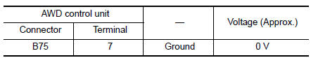
1.CHECK AWD SOLENOID POWER SUPPLY (1)
- Turn the ignition switch OFF.
- Disconnect AWD control unit harness connector.
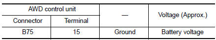
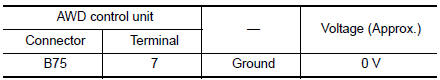
- Check the voltage between AWD control unit harness connector and ground.
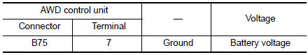
- Turn the ignition switch ON.
CAUTION: Never start the engine.
- Check the voltage between AWD control unit harness connector and ground.
Is the inspection result normal?
YES >> GO TO 3.
NO >> GO TO 2.
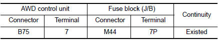
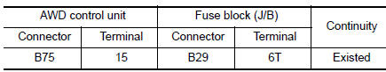
2.CHECK AWD SOLENOID POWER SUPPLY (2)
- Turn the ignition switch OFF.
- Check the 10A fuse (#16).
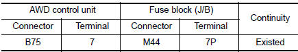
- Disconnect fuse block (J/B) harness connector.
- Check the continuity between AWD control unit harness connector and fuse block (J/B) harness connector.
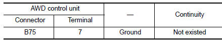
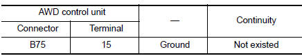
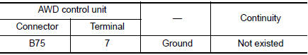
- Check the continuity between AWD control unit harness connector and the ground.
Is the inspection result normal? YES >> Perform the trouble diagnosis for power supply circuit. Refer to PG-4, "Wiring Diagram — Battery Power Supply —".
NO >> Repair or replace error-detected parts.
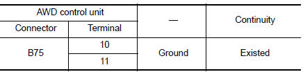
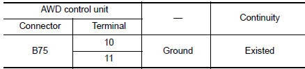
3.CHECK AWD SOLENOID GROUND
Check the continuity between AWD control unit harness connector and ground.
Is the inspection result normal? YES >> GO TO 4.
NO >> Repair or replace error-detected parts.
4.CHECK AWD SOLENOID CIRCUIT (1)
Check the resistance between AWD control unit harness connector.
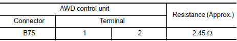
Is the inspection result normal? YES >> GO TO 7.
NO >> GO TO 5.
5.CHECK AWD SOLENOID CIRCUIT (2)
- Remove AWD solenoid harness connector.
- Check the continuity between AWD control unit harness connector and AWD solenoid harness connector.
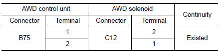
- Check the continuity between AWD control unit harness connector and the ground.
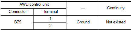
Is the inspection result normal? YES >> GO TO 6.
NO >> Repair or replace error-detected parts.
6.CHECK AWD SOLENOID
Check AWD solenoid. Refer to DLN-40, "Component Inspection".
Is the inspection result normal? YES >> GO TO 7.
NO >> AWD solenoid is malfunctioning. Replace electric controlled coupling. Refer to DLN-114, "Removal and Installation".
7.CHECK TERMINALS AND HARNESS CONNECTORS
- Check AWD control unit pin terminals for damage or loose connection with harness connector.
- Check AWD solenoid pin terminals for damage or loose connection with harness connector.
Is the inspection result normal? YES >> Replace AWD control unit. Refer to DLN-67, "Removal and Installation".
NO >> Repair or replace error-detected parts.
Component Inspection
1.CHECK AWD SOLENOID
- Turn the ignition switch OFF.
- Disconnect AWD solenoid harness connector.
- Check the resistance between AWD solenoid harness connector terminals.
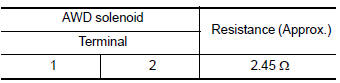
Is the inspection result normal? YES >> INSPECTION END
NO >> AWD solenoid is malfunctioning. Replace electric controlled coupling. Refer to DLN-114, "Removal and Installation".
C1209 MODE SW
DTC Description
DTC DETECTION LOGIC
| DTC No. | CONSULT screen terms (Trouble diagnosis content) | DTC detecting condition |
| C1209 | MODE SW (Mode switch) | More than two switch inputs are simultaneously detected due to short circuit of AWD lock switch. |
POSSIBLE CAUSE
Malfunction of AWD lock switch or AWD lock switch circuit.
FAIL-SAFE
AWD control changes to front-wheel drive immediately, then AWD control stops, and the vehicle becomes front-wheel drive.
DTC CONFIRMATION PROCEDURE
1.PRECONDITIONING
If “DTC CONFIRMATION PROCEDURE” has been previously conducted, always turn ignition switch OFF and wait at least 10 seconds before conducting the next test.
>> GO TO 2.
2.DTC REPRODUCTION PROCEDURE
 With CONSULT
- Turn the ignition switch OFF to ON.
- Perform self-diagnosis for “ALL MODE AWD/4WD”.
Is DTC “C1209” detected? YES >> Proceed to diagnosis procedure. Refer to DLN-41, "Diagnosis Procedure".
NO-1 >> To check malfunction symptom before repair: Refer to GI-41, "Intermittent Incident".
NO-2 >> Confirmation after repair: INSPECTION END
Diagnosis Procedure
1.CHECK AWD LOCK SWITCH
Check AWD lock switch. Refer to DLN-42, "Component Inspection".
Is the inspection result normal? YES >> GO TO 2.
NO >> Replace AWD lock switch. Refer to DLN-68, "Removal and Installation".
2.CHECK AWD LOCK SWITCH CIRCUIT (1)
Check the continuity between AWD lock switch harness connector and ground.
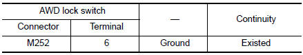
Is the inspection result normal? YES >> GO TO 3.
NO >> Repair or replace damaged parts.
3.CHECK AWD LOCK SWITCH CIRCUIT (2)
- Disconnect AWD control unit harness connector.
- Check the continuity between AWD control unit harness connector and AWD lock switch harness connector.
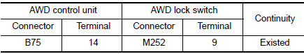
- Check the continuity between AWD control unit harness connector and ground.
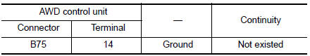
Is the inspection result normal? YES >> GO TO 4.
NO >> Repair or replace damaged parts.
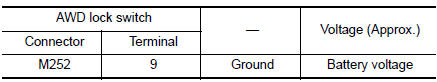
4.CHECK AWD CONTROL UNIT OUTPUT SIGNAL
- Connect AWD control unit harness connector.
- Turn the ignition switch ON.
CAUTION: Never start the engine.
- Check the voltage between AWD lock switch harness connector and ground.
Is the inspection result normal? YES >> Check each harness connector pin terminal for disconnection.
NO >> Replace AWD control unit. Refer to DLN-67, "Removal and Installation".
Component Inspection
1.CHECK AWD LOCK SWITCH
- Turn the ignition switch OFF.
- Remove AWD lock switch.
- Check the continuity between AWD lock switch connector terminals.
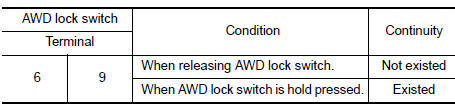
Is the inspection result normal? YES >> INSPECTION END
NO >> Replace AWD lock switch. Refer to DLN-68, "Removal and Installation".
C1210 ECM
DTC Description
DTC DETECTION LOGIC
| DTC No. | CONSULT screen terms (Trouble diagnosis content) | DTC detecting condition |
| C1210 | ENGINE SIGNAL 1 (Engine signal 1) | Malfunction related to engine signal has been detected. |
POSSIBLE CAUSE
Malfunction of engine control system
FAIL-SAFE
AWD control changes to front-wheel drive gradually (rear-wheels still have some driving torque), then AWD control stops, and the vehicle becomes front-wheel drive.
DTC CONFIRMATION PROCEDURE
1.PRECONDITIONING
If “DTC CONFIRMATION PROCEDURE” has been previously conducted, always turn ignition switch OFF and wait at least 10 seconds before conducting the next test.
>> GO TO 2.
2.DTC REPRODUCTION PROCEDURE
 With CONSULT
- Drive the vehicle for a while.
- Perform self-diagnosis for “ALL MODE AWD/4WD”.
Is DTC “C1210” detected? YES >> Proceed to diagnosis procedure. Refer to DLN-43, "Diagnosis Procedure".
NO-1 >> To check malfunction symptom before repair: Refer to GI-41, "Intermittent Incident".
NO-2 >> Confirmation after repair: INSPECTION END
Diagnosis Procedure
1.PERFORM ECM SELF-DIAGNOSIS
 With CONSULT
Perform self-diagnosis for “ENGINE”.
Is any DTC detected? YES >> Check the DTC. Refer to EC-93, "DTC Index".
NO >> GO TO 2.
2.CHECK TERMINALS AND HARNESS CONNECTORS
Check AWD control unit pin terminals for damage or loose connection with harness connector.
Is inspection result normal? YES >> After turning the ignition switch OFF, perform DTC confirmation procedure again. If DTC “C1210” is detected, Replace AWD control unit. Refer to DLN-67, "Removal and Installation".
NO >> Repair or replace error-detected parts.
P1804 AWD CONTROL UNIT
DTC Description
DTC DETECTION LOGIC
| DTC No. | CONSULT screen terms (Trouble diagnosis content) | DTC detecting condition |
| P1804 | CONTROL UNIT (Control unit) | Malfunction is detected in the memory (EEPROM) system of AWD control unit. |
POSSIBLE CAUSE
Internal malfunction of AWD control unit.
FAIL-SAFE
AWD control changes to front-wheel drive immediately, then AWD control stops, and the vehicle becomes front-wheel drive.
DTC CONFIRMATION PROCEDURE
1.PRECONDITIONING
If “DTC CONFIRMATION PROCEDURE” has been previously conducted, always turn ignition switch OFF and wait at least 10 seconds before conducting the next test.
>> GO TO 2.
2.DTC REPRODUCTION PROCEDURE
 With CONSULT
- Turn the ignition switch ON.
- Perform self-diagnosis for “ALL MODE AWD/4WD”.
Is DTC “P1804” detected? YES >> Proceed to diagnosis procedure. Refer to DLN-44, "Diagnosis Procedure".
NO-1 >> To check malfunction symptom before repair: Refer to GI-41, "Intermittent Incident".
NO-2 >> Confirmation after repair: INSPECTION END
Diagnosis Procedure
1.REPLACE AWD CONTROL UNIT
CAUTION: Replace AWD control unit when DTC “P1804” is detected simultaneously with other items.
>> Replace AWD control unit. Refer DLN-67, "Removal and Installation".
P1808 WHEEL SPEED SENSOR
DTC Description
DTC DETECTION LOGIC
| DTC No. | CONSULT screen terms (Trouble diagnosis content) | DTC detecting condition |
| P1808 | VHCL SPEED SEN-ABS (Vehicle speed sensor-ABS) |
|
POSSIBLE CAUSE
- ABS malfunction
- Internal malfunction of AWD control unit
FAIL-SAFE
AWD control changes to front-wheel drive gradually (rear-wheels still have some driving torque), then AWD control stops, and the vehicle becomes front-wheel drive.
DTC CONFIRMATION PROCEDURE
1.PRECONDITIONING
If “DTC CONFIRMATION PROCEDURE” has been previously conducted, always turn ignition switch OFF and wait at least 10 seconds before conducting the next test.
>> GO TO 2.
2.DTC REPRODUCTION PROCEDURE
 With CONSULT
- Turn the ignition switch ON.
- Perform self-diagnosis for “ALL MODE AWD/4WD”.
Is DTC “P1808” detected? YES >> Proceed to diagnosis procedure. Refer to DLN-45, "Diagnosis Procedure".
NO-1 >> To check malfunction symptom before repair: Refer to GI-41, "Intermittent Incident".
NO-2 >> Confirmation after repair: INSPECTION END
Diagnosis Procedure
1.PERFORM ABS ACTUATOR AND ELECTRIC UNIT (CONTROL UNIT) SELF-DIAGNOSIS
 With CONSULT
Perform self-diagnosis for “ABS”.
Is any DTC detected? YES >> Check the DTC. Refer to BRC-55, "DTC Index".
NO >> GO TO 2.
2.CHECK TERMINALS AND HARNESS CONNECTORS
Check AWD control unit pin terminals for damage or loose connection with harness connector.
Is inspection result normal? YES >> After turning the ignition switch OFF, perform DTC confirmation procedure again. If DTC “P1808” is detected, Replace AWD control unit. Refer to DLN-67, "Removal and Installation".
NO >> Repair or replace error-detected parts.
P1809 AWD CONTROL UNIT
DTC Description
DTC DETECTION LOGIC
| DTC No. | CONSULT screen terms (Trouble diagnosis content) | DTC detecting condition |
| P1809 | CONTROL UNIT (Control unit) | AD converter system of AWD control unit is malfunctioning. |
POSSIBLE CAUSE
Internal malfunction of AWD control unit
FAIL-SAFE
AWD control changes to front-wheel drive immediately, then AWD control stops, and the vehicle becomes front-wheel drive.
DTC CONFIRMATION PROCEDURE
1.PRECONDITIONING
If “DTC CONFIRMATION PROCEDURE” has been previously conducted, always turn ignition switch OFF and wait at least 10 seconds before conducting the next test.
>> GO TO 2.
2.DTC REPRODUCTION PROCEDURE
 With CONSULT
- Turn the ignition switch ON.
- Perform self-diagnosis for “ALL MODE AWD/4WD”.
Is DTC “P1809” detected? YES >> Proceed to diagnosis procedure. Refer to DLN-46, "Diagnosis Procedure".
NO-1 >> To check malfunction symptom before repair: Refer to GI-41, "Intermittent Incident".
NO-2 >> Confirmation after repair: INSPECTION END
Diagnosis Procedure
1.REPLACE AWD CONTROL UNIT
CAUTION: Replace AWD control unit when DTC “P1809” is detected simultaneously with other items.
>> Replace AWD control unit. Refer DLN-67, "Removal and Installation".
P1811 BATTERY VOLTAGE
DTC Description
DTC DETECTION LOGIC
| DTC No. | CONSULT screen terms (Trouble diagnosis content) | DTC detecting condition |
| P1811 | BATTERY VOLTAGE (Battery voltage) | When engine is running and AWD control unit power supply is less than 9 V or higher than 16 V. |
POSSIBLE CAUSE
- Malfunction of AWD control unit power supply circuit (open or short)
- Battery power supply
- Ignition power supply
- Internal malfunction of AWD control unit
FAIL-SAFE
AWD control changes to front-wheel drive immediately, then AWD control stops, and the vehicle becomes front-wheel drive.
DTC CONFIRMATION PROCEDURE
1.PRECONDITIONING
If “DTC CONFIRMATION PROCEDURE” has been previously conducted, always turn ignition switch OFF and wait at least 10 seconds before conducting the next test.
>> GO TO 2.
2.DTC REPRODUCTION PROCEDURE
With CONSULT
- Turn the ignition switch ON.
- Perform self-diagnosis for “ALL MODE AWD/4WD”.
Is DTC “P1811” detected? YES >> Proceed to diagnosis procedure. Refer to DLN-47, "Diagnosis Procedure".
NO-1 >> To check malfunction symptom before repair: Refer to GI-41, "Intermittent Incident".
NO-2 >> Confirmation after repair: INSPECTION END
Diagnosis Procedure
1.CHECK AWD CONTROL UNIT POWER SUPPLY (1)
- Turn the ignition switch OFF.
- Disconnect AWD control unit harness connector.
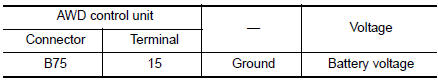
- Check the voltage between AWD control unit harness connector and ground.
- Turn the ignition switch ON.
CAUTION: Never start the engine.
- Check the voltage between AWD control unit harness connector and ground.
Is the inspection result normal? YES >> GO TO 3.
NO >> GO TO 2.
2.CHECK AWD CONTROL UNIT POWER SUPPLY (2)
- Turn the ignition switch OFF.
- Check the 10A fuse (#30).
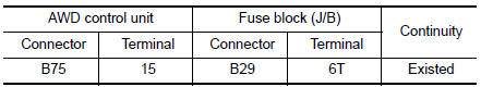
- Disconnect fuse block (J/B) harness connector.
- Check the continuity between AWD control unit harness connector and fuse block (J/B) harness connector.
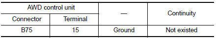
- Check the continuity between AWD control unit harness connector and the ground.
Is the inspection result normal? YES >> Perform the trouble diagnosis for ignition power supply circuit. Refer to PG-15, "Wiring Diagram — Ignition Power Supply —".
NO >> Repair or replace error-detected parts.
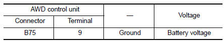
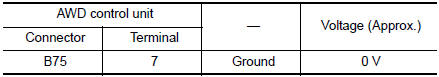
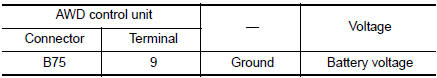
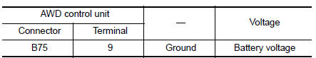
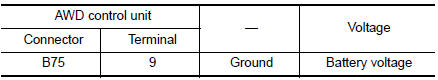
3.CHECK AWD CONTROL UNIT POWER SUPPLY (3)
- Turn the ignition switch OFF.
- Check the voltage between AWD control unit harness connector and ground.
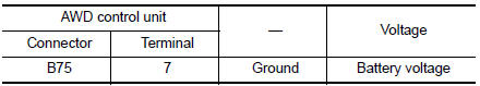
- Turn the ignition switch ON.
CAUTION: Never start the engine.
- Check the voltage between AWD control unit harness connector and ground.
Is the inspection result normal? YES >> GO TO 5.
NO >> GO TO 4.
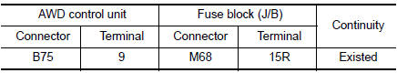
4.CHECK AWD CONTROL UNIT POWER SUPPLY (4)
- Turn the ignition switch OFF.
- Check the 5A fuse (#9).
- Disconnect fuse block (J/B) harness connector.
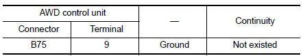
- Check the continuity between AWD control unit harness connector and fuse block (J/B) harness connector.
- Check the continuity between AWD control unit harness connector and the ground.
Is the inspection result normal? YES >> Perform the trouble diagnosis for power supply circuit. Refer to PG-4, "Wiring Diagram — Battery Power Supply —".
NO >> Repair or replace error-detected parts.
5.CHECK AWD CONTROL UNIT GROUND
- Turn the ignition switch OFF.
- Check the continuity between AWD control unit harness connector and ground.
Is the inspection result normal? YES >> GO TO 6.
NO >> Repair or replace error-detected parts.
6.CHECK TERMINALS AND HARNESS CONNECTORS
Check AWD control unit pin terminals for damage or loose connection with harness connector.
Is the inspection result normal? YES >> After turning the ignition switch OFF, perform DTC confirmation procedure again. When DTC “P1811” is detected, Replace AWD control unit. Refer to DLN-67, "Removal and Installation".
NO >> Repair or replace error-detected parts.
P181B INCOMPLETE SELFSHUT
DTC Description
DTC DETECTION LOGIC
| DTC No. | CONSULT screen terms (Trouble diagnosis content) | DTC detecting condition |
| P181B | INCOMP SELF SHUT (Incomplete self shut) | When ignition switch is ON, self-shut of AWD control unit was incomplete. |
POSSIBLE CAUSE
- Malfunction of AWD control unit power supply circuit (open or short)
- Battery power supply
- Ignition power supply
- Internal malfunction of AWD control unit
FAIL-SAFE
No impact to vehicle behavior.
DTC CONFIRMATION PROCEDURE
1.PRECONDITIONING
If “DTC CONFIRMATION PROCEDURE” has been previously conducted, always turn ignition switch OFF and wait at least 10 seconds before conducting the next test.
>> GO TO 2.
2.DTC REPRODUCTION PROCEDURE
 With CONSULT
- Turn the ignition switch ON.
- Perform self-diagnosis for “ALL MODE AWD/4WD”.
Is DTC “P181B” detected? YES >> Proceed to diagnosis procedure. Refer to DLN-50, "Diagnosis Procedure".
NO-1 >> To check malfunction symptom before repair: Refer to GI-41, "Intermittent Incident".
NO-2 >> Confirmation after repair: INSPECTION END
Diagnosis Procedure
1.CHECK AWD CONTROL UNIT POWER SUPPLY (1)
- Turn the ignition switch OFF.
- Disconnect AWD control unit harness connector.
- Check the voltage between AWD control unit harness connector and ground.
- Turn the ignition switch ON.
CAUTION: Never start the engine.
- Check the voltage between AWD control unit harness connector and ground.
Is the inspection result normal?
YES >> GO TO 3.
NO >> GO TO 2.
2.CHECK AWD CONTROL UNIT POWER SUPPLY (2)
- Turn the ignition switch OFF.
- Check the 10A fuse (#30).
- Disconnect fuse block (J/B) harness connector.
- Check the continuity between AWD control unit harness connector and fuse block (J/B) harness connector.
- Check the continuity between AWD control unit harness connector and the ground.
Is the inspection result normal? YES >> Perform the trouble diagnosis for ignition power supply circuit. Refer to PG-15, "Wiring Diagram — Ignition Power Supply —".
NO >> Repair or replace error-detected parts.
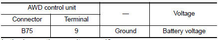
3.CHECK AWD CONTROL UNIT POWER SUPPLY (3)
- Turn the ignition switch OFF.
- Check the voltage between AWD control unit harness connector and ground.
- Turn the ignition switch ON.
CAUTION: Never start the engine.
- Check the voltage between AWD control unit harness connector and ground.
Is the inspection result normal? YES >> GO TO 5.
NO >> GO TO 4.
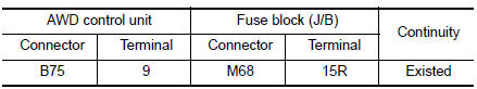
4.CHECK AWD CONTROL UNIT POWER SUPPLY (4)
- Turn the ignition switch OFF.
- Check the 5A fuse (#9).
- Disconnect fuse block (J/B) harness connector.
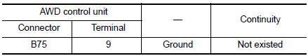
- Check the continuity between AWD control unit harness connector and fuse block (J/B) harness connector.
- Check the continuity between AWD control unit harness connector and the ground
Is the inspection result normal? YES >> Perform the trouble diagnosis for power supply circuit. Refer to PG-4, "Wiring Diagram — Battery Power Supply —".
NO >> Repair or replace error-detected parts.
5.CHECK AWD CONTROL UNIT GROUND
- Turn the ignition switch OFF.
- Check the continuity between AWD control unit harness connector and ground.
Is the inspection result normal? YES >> GO TO 6.
NO >> Repair or replace error-detected parts.
6.CHECK TERMINALS AND HARNESS CONNECTORS
Check AWD control unit pin terminals for damage or loose connection with harness connector.
Is the inspection result normal? YES >> After turning the ignition switch OFF, perform DTC confirmation procedure again. When DTC “P181B” is detected, Replace AWD control unit. Refer to DLN-67, "Removal and Installation".
NO >> Repair or replace error-detected parts.
P181D ENGINE TORQUE SIGNAL
DTC Description
DTC DETECTION LOGIC
| DTC No. | CONSULT screen terms (Trouble diagnosis content) | DTC detecting condition |
| P181D | ENGINE SYSTEM (Engine system) | Malfunction related to engine signal has been detected. |
POSSIBLE CAUSE
- Malfunction of engine control system
- Internal malfunction of AWD control unit
FAIL-SAFE
AWD control changes to front-wheel drive gradually (rear-wheels still have some driving torque), then AWD control stops, and the vehicle becomes front-wheel drive.
DTC CONFIRMATION PROCEDURE
1.PRECONDITIONING
If “DTC CONFIRMATION PROCEDURE” has been previously conducted, always turn ignition switch OFF and wait at least 10 seconds before conducting the next test.
>> GO TO 2.
2.DTC REPRODUCTION PROCEDURE
With CONSULT
- Drive the vehicle for a while.
- Stop the vehicle.
- Perform self-diagnosis for “ALL MODE AWD/4WD”.
Is DTC “P181D” detected? YES >> Proceed to diagnosis procedure. Refer to DLN-53, "Diagnosis Procedure".
NO-1 >> To check malfunction symptom before repair: Refer to GI-41, "Intermittent Incident".
NO-2 >> Confirmation after repair: INSPECTION END
Diagnosis Procedure
1.PERFORM ECM SELF-DIAGNOSIS
 With CONSULT
Perform self-diagnosis for “ENGINE”.
Is any DTC detected? YES >> Check the DTC. Refer to EC-93, "DTC Index".
NO >> GO TO 2.
2.CHECK TERMINALS AND HARNESS CONNECTORS
Check AWD control unit pin terminals for damage or loose connection with harness connector.
Is inspection result normal? YES >> After turning the ignition switch OFF, perform DTC confirmation procedure again. If DTC “P181D” is detected, Replace AWD control unit. Refer to DLN-67, "Removal and Installation".
NO >> Repair or replace error-detected parts.
P181F INCOMPLETE CALIBRATION
DTC Description
DTC DETECTION LOGIC
| DTC No. | CONSULT screen terms (Trouble diagnosis content) | DTC detecting condition |
| P181F | INCOMP CALIBRATION (incomplete calibration) | When incomplete writing unit characteristics of electric controlled coupling are detected. |
POSSIBLE CAUSE
Writing unit characteristics are incomplete.
FAIL-SAFE
AWD control changes to front-wheel drive immediately, then AWD control stops, and the vehicle becomes front-wheel drive.
DTC CONFIRMATION PROCEDURE
1.PRECONDITIONING
If “DTC CONFIRMATION PROCEDURE” has been previously conducted, always turn ignition switch OFF and wait at least 10 seconds before conducting the next test.
>> GO TO 2.
2.DTC REPRODUCTION PROCEDURE
With CONSULT
- Turn the ignition switch OFF to ON.
- Perform self-diagnosis for “ALL MODE AWD/4WD”.
Is DTC “P181F” detected? YES >> Proceed to diagnosis procedure. Refer to DLN-54, "Diagnosis Procedure".
NO-1 >> To check malfunction symptom before repair: Refer to GI-41, "Intermittent Incident".
NO-2 >> Confirmation after repair: INSPECTION END
Diagnosis Procedure
1.PERFORM WRITING UNIT CHARACTERISTICS
- Erase self-diagnostic result for “ALL MODE AWD/4WD”.
- Perform writing unit characteristics. Refer to DLN-35, "Work Procedure".
- Turn the ignition switch OFF to ON.
- Perform self-diagnosis for “ALL MODE AWD/4WD”.
Is any DTC except “P181F” detected? YES >> Perform trouble diagnosis for detected DTC. Refer to DLN-23, "DTC Index".
NO >> GO TO 2.
2.PERFORM SELF-DIAGNOSIS AGAIN
With CONSULT
Perform “DTC CONFIRMATION PROCEDURE” (self-diagnosis) again. Refer to DLN-54, "DTC Description".
Is DTC “P181F” detected? YES >> Replace AWD control unit. Refer to DLN-67, "Removal and Installation".
NO >> Check AWD control unit pin terminals for damage or loose connection with harness connector. If any items are damaged, repair or replace error-detected parts.
U1000 CAN COMM CIRCUIT
DTC Description
CAN (Controller Area Network) is a serial communication line for real time application. It is an on-vehicle multiplex communication line with high data communication speed and excellent error detection ability. Many electronic control units are equipped onto a vehicle, and each control unit shares information and links with other control units during operation (not independent). In CAN communication, control units are connected with 2 communication lines (CAN-H line, CAN-L line) allowing a high rate of information transmission with less wiring.
Each control unit communicate data but selectively reads required data only.
DTC DETECTION LOGIC
| DTC No. | CONSULT screen terms (Trouble diagnosis content) | DTC detecting condition |
| U1000 | CAN COMM CIRCUIT (CAN communication circuit) | AWD control unit is not transmitting/receiving CAN communication signal for 2 seconds or more. |
POSSIBLE CAUSE
- CAN communication error
- Internal malfunction of AWD control unit
FAIL-SAFE
AWD control changes to front-wheel drive gradually (rear-wheels still have some driving torque), then AWD control stops, and the vehicle becomes front-wheel drive.
DTC CONFIRMATION PROCEDURE
1.PRECONDITIONING
If “DTC CONFIRMATION PROCEDURE” has been previously conducted, always turn ignition switch OFF and wait at least 10 seconds before conducting the next test.
>> GO TO 2.
2.DTC REPRODUCTION PROCEDURE
With CONSULT
- Turn the ignition switch OFF to ON.
- Perform self-diagnosis for “ALL MODE AWD/4WD”.
Is DTC “U1000” detected? YES >> Proceed to diagnosis procedure. Refer to DLN-55, "Diagnosis Procedure".
NO-1 >> To check malfunction symptom before repair: Refer to GI-41, "Intermittent Incident".
NO-2 >> Confirmation after repair: INSPECTION END
Diagnosis Procedure
Proceed to LAN-17, "Trouble Diagnosis Flow Chart".
U1010 CONTROL UNIT (CAN)
DTC Description
CAN (Controller Area Network) is a serial communication line for real time application. It is an on-vehicle multiplex communication line with high data communication speed and excellent error detection ability. Many electronic control units are equipped onto a vehicle, and each control unit shares information and links with other control units during operation (not independent). In CAN communication, control units are connected with 2 communication lines (CAN-H line, CAN-L line) allowing a high rate of information transmission with less wiring.
Each control unit communicate data but selectively reads required data only.
DTC DETECTION LOGIC
| DTC No. | CONSULT screen terms (Trouble diagnosis content) | DTC detecting condition |
| U1010 | CONTROL UNIT (CAN) [Control unit (CAN)] | Detecting error during the initial diagnosis of CAN controller of AWD control unit. |
POSSIBLE CAUSE
Internal malfunction of AWD control unit
FAIL-SAFE
AWD control changes to front-wheel drive gradually (rear-wheels still have some driving torque), then AWD control stops, and the vehicle becomes front-wheel drive.
DTC CONFIRMATION PROCEDURE
1.PRECONDITIONING
If “DTC CONFIRMATION PROCEDURE” has been previously conducted, always turn ignition switch OFF and wait at least 10 seconds before conducting the next test.
>> GO TO 2.
2.DTC REPRODUCTION PROCEDURE
With CONSULT
- Turn the ignition switch OFF to ON.
- Perform self-diagnosis for “ALL MODE AWD/4WD”.
Is DTC “U1010” detected?
YES >> Proceed to diagnosis procedure. Refer to DLN-56, "Diagnosis Procedure".
NO-1 >> To check malfunction symptom before repair: Refer to GI-41, "Intermittent Incident".
NO-2 >> Confirmation after repair: INSPECTION END
Diagnosis Procedure
1.CHECK AWD CONTROL UNIT
Check AWD control unit harness connector for disconnection and deformation.
Is the inspection result normal? YES >> Replace AWD control unit. Refer to DLN-67, "Removal and Installation".
NO >> Repair or replace error-detected parts.
POWER SUPPLY AND GROUND CIRCUIT
Diagnosis Procedure
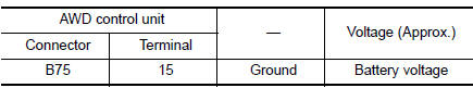
1.CHECK AWD CONTROL UNIT POWER SUPPLY (1)
- Turn the ignition switch OFF.
- Disconnect AWD control unit harness connector.
- Check the voltage between AWD control unit harness connector and ground.
- Turn the ignition switch ON.
CAUTION: Never start the engine.
- Check the voltage between AWD control unit harness connector and ground.
Is the inspection result normal? YES >> GO TO 3.
NO >> GO TO 2.
2.CHECK AWD CONTROL UNIT POWER SUPPLY (2)
- Turn the ignition switch OFF.
- Check the 10A fuse (#30).
- Disconnect fuse block (J/B) harness connector.
- Check the continuity between AWD control unit harness connector and fuse block (J/B) harness connector.
- Check the continuity between AWD control unit harness connector and the ground.
Is the inspection result normal? YES >> Perform the trouble diagnosis for ignition power supply circuit. Refer to PG-15, "Wiring Diagram — Ignition Power Supply —".
NO >> Repair or replace error-detected parts.
3.CHECK AWD CONTROL UNIT POWER SUPPLY (3)
- Turn the ignition switch OFF.
- Check the voltage between AWD control unit harness connector and ground.
- Turn the ignition switch ON.
CAUTION: Never start the engine.
- Check the voltage between AWD control unit harness connector and ground.
Is the inspection result normal? YES >> GO TO 5.
NO >> GO TO 4.
4.CHECK AWD CONTROL UNIT POWER SUPPLY (4)
- Turn the ignition switch OFF.
- Check the 5A fuse (#9).
- Disconnect fuse block (J/B) harness connector.
- Check the continuity between AWD control unit harness connector and fuse block (J/B) harness connector.
- Check the continuity between AWD control unit harness connector and the ground.
Is the inspection result normal? YES >> Perform the trouble diagnosis for power supply circuit. Refer to PG-4, "Wiring Diagram — Battery Power Supply —".
NO >> Repair or replace error-detected parts.
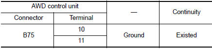
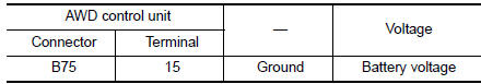
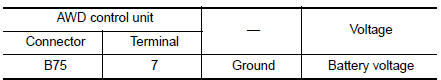
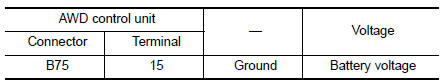
5.CHECK AWD SOLENOID POWER SUPPLY (1)
- Turn the ignition switch OFF.
- Check the voltage between AWD control unit harness connector and ground.
- Turn the ignition switch ON.
CAUTION: Never start the engine.
- Check the voltage between AWD control unit harness connector and ground.
Is the inspection result normal? YES >> GO TO 7.
NO >> GO TO 6.
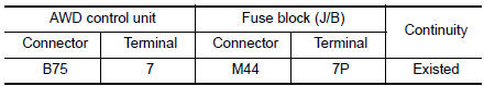
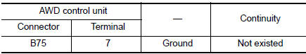
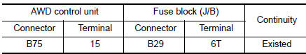
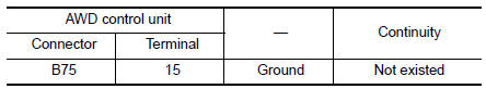
6.CHECK AWD SOLENOID POWER SUPPLY (2)
- Turn the ignition switch OFF.
- Check the 10A fuse (#16).
- Disconnect fuse block (J/B) harness connector.
- Check the continuity between AWD control unit harness connector and fuse block (J/B) harness connector.
- Check the continuity between AWD control unit harness connector and the ground.
Is the inspection result normal? YES >> Perform the trouble diagnosis for power supply circuit. Refer to PG-4, "Wiring Diagram — Battery Power Supply —".
NO >> Repair or replace error-detected parts.
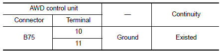
7.CHECK AWD CONTROL UNIT GROUND
- Turn the ignition switch OFF.
- Check the continuity between AWD control unit harness connector and ground.
Is the inspection result normal? YES >> INSPECTION END
NO >> Repair or replace error-detected parts.
 Basic inspection
DIAGNOSIS AND REPAIR WORK FLOW
Work Flow
DETAILED FLOW
1.INTERVIEW FROM THE CUSTOMER
Clarify customer complaints before inspection. First of all, perform an
interview utilizing DLN-32, "Dia ...
 Symptom diagnosis
HEAVY TIGHT-CORNER BRAKING SYMPTOM OCCURS
Description
Heavy tight-corner braking symptom occurs when the vehicle is driven and the
steering wheel is turned fully to
either side after the engine i ...
Other materials:
The parking brake release warning continues sounding, or
does not sound
Description
The parking brake warning buzzer sounds continuously during vehicle
travel though the parking brake is
released.
The parking brake warning buzzer does not sound at all even though
driving the vehicle with the parking
brake applied.
Diagnosis Procedure
1. CHECK P ...
Location of plastic parts
Precautions for Plastics
CAUTION:
When repairing and painting a portion of the body adjacent to
plastic parts, consider their characteristics (influence of heat
and solvent) and remove them if necessary or take suitable measures to
protect them.
Plastic parts should be ...
B0029 side curtain air bag module RH
DTC Logic
DTC DETECTION LOGIC
CONSULT name
DTC
DTC detecting condition
Repair order
CURTAIN AIRBAG MODULE RH CIRCUIT
[OPEN]
B0029
RH side curtain air bag module circuit
is open.
Refer to SRC-57, "Diagnosis Procedure".
CURTA ...
