Nissan Rogue Service Manual: Diagnosis and repair work flow
Work Flow
NOTE: ŌĆ£DTCŌĆØ includes DTC at the 1st trip.
1.OBTAIN INFORMATION ABOUT SYMPTOM
Refer to TM-80, "Diagnostic Work Sheet" and interview the customer to obtain the malfunction information (conditions and environment when the malfunction occurred) as much as possible when the customer brings in the vehicle.
>> GO TO 2.
2.CHECK DTC
- Before checking the malfunction, check whether any DTC exists.
- If DTC exists, perform the following operations.
- Records the DTCs. (Print out using CONSULT and affix to the Work Order Sheet.)
- Erase DTCs.
- Check the relation between the cause found by DTC and the malfunction information from customer. TM- 186, "Symptom Table" can be used effectively.
- Check the relevant information including STI, etc.
Do malfunction information and DTC exists? Malfunction information and DTC exists.>>GO TO 3.
Malfunction information exists but no DTC.>>GO TO 4.
No malfunction information, but DTC exists.>>GO TO 5.
3.REPRODUCE MALFUCTION SYSTEM
Check the malfunction described by the customer on the vehicle.
Check if the behavior is fail safe or normal operation. Refer to TM-58, "Fail-safe".
Interview sheet can be used effectively when reproduce malfunction conditions. Refer to TM-80, "Diagnostic Work Sheet".
Verify the relationship between the symptom and the conditions in which the malfunction described by the customer occurs.
>> GO TO 5.
4.REPRODUCE MALFUNCTION SYMPTOM
Check the malfunction described by the customer on the vehicle.
Check if the behavior is fail safe or normal operation. Refer to TM-58, "Fail-safe".
Interview sheet can be used effectively when reproduce malfunction conditions. Refer to TM-80, "Diagnostic Work Sheet".
Verify the relationship between the symptom and the conditions in which the malfunction described by the customer occurs.
>> GO TO 6.
5.PERFORM ŌĆ£DTC CONFIRMATION PROCEDUREŌĆØ
Perform ŌĆ£DTC CONFIRMATION PROCEDUREŌĆØ of the appropriate DTC to check if DTC is detected again.
Refer to TM-62, "DTC Inspection Priority Chart" when multiple DTCs are detected, and then determine the order for performing the diagnosis.
Is any DTC detected? YES >> GO TO 7.
NO >> Follow GI-41, "Intermittent Incident" to check.
6.IDENTIFY MALFUNCTIONING SYSTEM WITH ŌĆ£DIAGNOSIS CHART BY SYMPTOMŌĆØ
Use TM-186, "Symptom Table" from the symptom inspection result in step 4. Then identify where to start performing the diagnosis based on possible causes and symptoms.
>> GO TO 8.
7.REPAIR OR REPLACE THE MALFUNCTIONING PARTS
Repair or replace the detected malfunctioning parts.
Reconnect parts or connector after repairing or replacing, and then erase DTC if necessary.
>> GO TO 8.
8.FINAL CHECK
Perform ŌĆ£DTC CONFIRMATION PROCEDUREŌĆØ again to make sure that the repair is correctly performed.
Check that malfunctions are not reproduced when obtaining the malfunction information from the customer, referring to the symptom inspection result in step 3 or 4.
Is DTC or malfunction symptom reproduced? YES-1 (DTC is reproduced.)>>GO TO 5.
YES-2 (Malfunction is reproduced.)>>GO TO 6.
NO >> Before delivering the vehicle to the customer, make sure that DTC is erased.
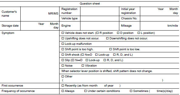
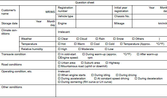
Diagnostic Work Sheet
DESCRIPTION
There are many operating conditions that may cause a malfunction of the transmission parts. By understanding those conditions properly, a quick and exact diagnosis can be achieved.
In general, perception of a problem varies depending on individuals.
Ask the customer about his/her concerns carefully. It is important to understand the phenomenon or status. To systemize all the information for the diagnosis, prepare the question sheet referring to the question points.
In some cases, multiple conditions that appear simultaneously may cause a DTC to be detected.
Worksheet Sample
 Basic inspection
...
 Additional service when replacing TCM
Description
Always perform the following items when the TCM is replaced.
TCM PROGRAMMING
Since vehicle specifications are not yet written in a new TCM, it
is necessary to write them w ...
Other materials:
Wiring diagram
POWER DOOR LOCK SYSTEM
Wiring Diagram
REMOTE KEYLESS ENTRY SYSTEM
Wiring Diagram
...
Instrument panel
Vent
Headlight/fog light (if so equipped)/turn signal switch
Meters, gauges, warning/indicator
lights and Vehicle Information Display
Windshield wiper/washer switch and rear window wiper/washer switch
/Ignition switch (if so equipped)
Push-button ...
Precaution
Precaution for Supplemental Restraint System (SRS) "AIR BAG" and "SEAT
BELT
PRE-TENSIONER"
The Supplemental Restraint System such as ŌĆ£AIR BAGŌĆØ and ŌĆ£SEAT BELT PRE-TENSIONERŌĆØ,
used along
with a front seat belt, helps to reduce the risk or severity of injury to the
...
