Nissan Rogue Service Manual: Center console assembly
Exploded View
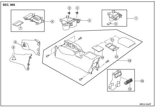
- Center console cup holder (without heated seats)
- Coin tray insert
- Center console cup holder (with heated seats)
- Front heated seat switch (RH)
- Front heated seat switch (LH)
- Shift selector finisher
- Shift selector finisher mat
- Center console side finisher (RH)
- Center console side finisher (LH)
- Center console tray
- Center console bin mat
- Center console rear brace finisher
- Center console assembly
- Rear center ventilator grille
- Center console rear finisher
 Metal clip
 Clip
Clip
 Pawl
Pawl
Removal and Installation
REMOVAL
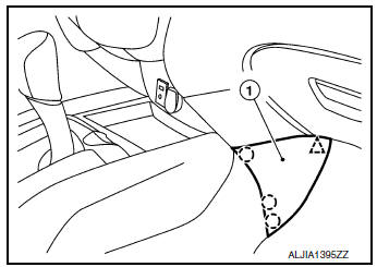
- Release clips and pawls using a suitable tool and remove center console side finisher (1) (LH/RH).
: Pawl
: Clip
NOTE: RH side shown; LH similar.
- Remove shift selector knob. Refer to TM-194, "Exploded View".
- Remove cluster lid C. Refer to IP-21, "Removal and Installation".
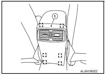
- Release clips using a suitable tool and remove center console
rear finisher (1).: Metal clip
- Remove center console screws (A).
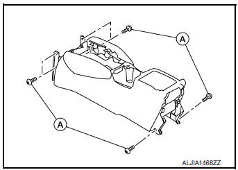
- Disconnect the harness connectors and remove center console.
INSTALLATION
Installation is in the reverse order of removal.
 Steering column covers
Removal and Installation
REMOVAL
Release gap hider (1) pawls from the steering column upper
cover (2).
: Pawl
Remove steering column cover screws (A)
NOTE:
Rotate steering w ...
 Cluster lid A
Removal and Installation
REMOVAL
Remove instrument lower panel LH. Refer to IP-22, "Removal and
Installation".
Remove instrument finisher A. Refer to IP-15, "INSTR ...
Other materials:
Fuel injector
Component Function Check
1.INSPECTION START
Turn ignition switch to START.
Are any cylinders ignited?
YES >> GO TO 2.
NO >> Proceed to EC-464, "Diagnosis Procedure".
2.CHECK FUEL INJECTOR FUNCTION
With CONSULT
Start engine.
Perform ŌĆ£POWER BALANCE ...
P117A air fuel ratio
DTC Description
DTC DETECTION LOGIC
DTC No.
CONSULT screen terms
(Trouble diagnosis content)
DTC detecting condition
P117A
AIR FUEL RATIO B1
(AIR FUEL RATIO B1)
ECM detects a lean/rich air fuel ratio state in any cylinder for a
specified
length of time.
...
Precaution
PRECAUTIONS
Precaution for Supplemental Restraint System (SRS) "AIR BAG" and "SEAT
BELT
PRE-TENSIONER"
The Supplemental Restraint System such as ŌĆ£AIR BAGŌĆØ and ŌĆ£SEAT BELT PRE-TENSIONERŌĆØ,
used along
with a front seat belt, helps to reduce the risk or severity of inj ...
