Nissan Rogue (T33) 2021-Present Service Manual: Can Fundamental :: Description
Outline
How to Use This Section
-
“CAN FUNDAMENTAL” of LAN Section describes the basic knowledge of the CAN communication system and the method of trouble diagnosis.
-
For information peculiar to a Nissan Ariya vehicle and inspection procedure, refer to “CAN”.
System (can Communication)
System Description
CAN (Controller Area Network) is a serial communication line for real time application. It is an on-Nissan Ariya vehicle multiplex communication line with high data communication speed and excellent error detection ability. Many electronic control units are equipped onto a Nissan Ariya vehicle, and each control unit shares information and links with other control units during operation (not independent). In CAN communication, control units are connected with 2 communication lines (CAN-H line, CAN-L line) allowing a high rate of information transmission with less wiring. Each control unit transmits/receives data but selectively reads required data only.
System (diag on Can)
System Description
SYSTEM DIAGRAM
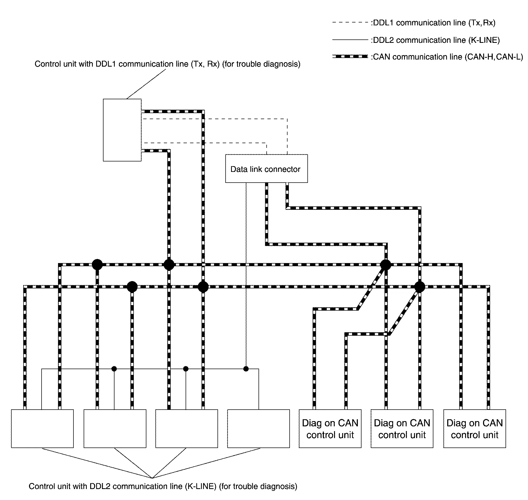
| Name | Harness | Description |
|---|---|---|
| DDL1 |
Tx Rx |
For communications with the diagnostic tool. (CAN-H and CAN-L are used for controlling) |
| DDL2 | K-LINE | For communications with the diagnostic tool. (CAN-H and CAN-L are used for controlling) |
| Diag on CAN |
CAN-H CAN-L |
For communications with the diagnostic tool. (CAN-H and CAN-L are also used for control and diagnoses.) |
DESCRIPTION
“Diag on CAN” is a diagnosis method which uses the CAN communication line for the communication between the control unit and the diagnostic tool.
Other materials:
Power Supply and Ground Circuit
Side Radar Front Lh
Diagnosis Procedure
CHECK FUSE
Check that the following fuse is not blown:
Signal name Fuse No.
Ignition power supply
9 (10 A)
Is the fuse blown?
YES>>
Replace the blown fuse after repairing the affected circuit.
NO>>
GO TO 2.
CHECK POWER SU ...
Writing of Calibration Data
Work Procedure
DESCRIPTIONIf only the around view monitor control unit
is replaced, the calibration data stored in the camera can be written
to the around view monitor control unit by selecting "Camera
Calibration" of "Work Support" mode in CONSULT.WORK PROCEDUREWRITE CALIBRATION DATA
With C ...
Removal and Installation. Hood Lock
Exploded View
Hood lock
Hood lock release cable assembly
Hood lock release handle
: Clip
: N·m (kg-m, in-lb)
: Body grease
Hood Lock
Removal and Installation
REMOVALRemove front grill cover. Refer to Removal and Installation.
Disconnect hood lock switch har ...