Nissan Rogue Service Manual: C1109 power and ground system
DTC Logic
DTC DETECTION LOGIC
| DTC | Display Item | Malfunction detected condition | Possible causes |
| C1109 | BATTERY VOLTAGE [ABNORMAL] |
|
|
DTC CONFIRMATION PROCEDURE
1.CHECK SELF-DIAGNOSTIC RESULT
 With CONSULT.
- Turn the ignition switch OFF to ON.
- Perform self-diagnostic result.
Is DTC C1109 detected? YES >> Proceed to diagnosis procedure. Refer to BRC-80, "Diagnosis Procedure".
NO >> Inspection End.
Diagnosis Procedure
Regarding Wiring Diagram information, refer to BRC-57, "Wiring Diagram".
1.CONNECTOR INSPECTION
- Turn ignition switch OFF.
- Disconnect ABS actuator and electric unit (control unit) connectors.
- Check connectors and terminals for deformation, disconnection, looseness or damage.
Is the inspection result normal? YES >> GO TO 2.
NO >> Repair or replace as necessary.
2.CHECK ABS ACTUATOR AND ELECTRIC UNIT (CONTROL UNIT) IGNITION POWER SUPPLY CIRCUIT
Check voltage between ABS actuator and electric unit (control unit) connector E125 terminal 28 and ground.
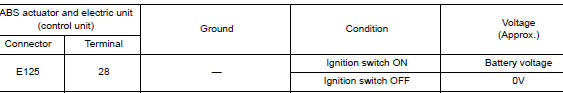
Is the inspection result normal? YES >> GO TO 3.
NO >> Repair or replace malfunctioning components.
3.CHECK ABS ACTUATOR AND ELECTRIC UNIT (CONTROL UNIT) BATTERY POWER SUPPLY CIRCUIT
Check voltage between ABS actuator and electric unit (control unit) connector E125 terminals 1, 25 and ground.

Is the inspection result normal? YES >> GO TO 4.
NO >> Repair or replace malfunctioning components.
4.CHECK ABS ACTUATOR AND ELECTRIC UNIT (CONTROL UNIT) GROUND CIRCUIT
- Turn ignition switch OFF.
- Check continuity between ABS actuator and electric unit (control unit) connector E125 terminals 13, 38 and ground.
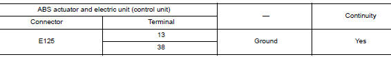
Is the inspection result normal? YES >> Replace ABS actuator and electric unit (control unit). Refer to BRC-136, "Removal and Installation".
NO >> Repair or replace malfunctioning components.
 C1105, C1106, C1107, C1108 wheel sensor
DTC Logic
DTC DETECTION LOGIC
DTC
Display Item
Malfunction detected condition
Possible causes
C1105
RR RH SENSOR-2
When distance between rear ...
 C1111 pump motor
DTC Logic
DTC DETECTION LOGIC
DTC
Display Item
Malfunction detected condition
Possible causes
C1111
PUMP MOTOR
When a malfunction is detected in motor or motor relay.
...
Other materials:
Diagnosis and repair work flow
Work Flow
OVERALL SEQUENCE
DETAILED FLOW
1.INTERVIEW THE CUSTOMER FOR THE SYMPTOM
Interview the customer for the symptom (the condition and the environment
when the incident/malfunction
occurs).
>> GO TO 2.
2.CHECK SYMPTOM
Check the symptom from the customer information.
> ...
Throttle valve closed position learning
Description
Throttle Valve Closed Position Learning is a function of ECM to learn the
fully closed position of the throttle
valve by monitoring the throttle position sensor output signal. It must be
performed each time the harness connector
of the electric throttle control actuator or ECM is ...
Removal and installation
HOOD
Exploded View
Hood hinge (RH)
Hood
Hood side seal
Hood front seal
Hood center seal
Bumper rubber
Hood insulator
Hood rod clamp
Hood support rod
Hood rod grommet
Hood hinge (LH)
HOOD ASSEMBLY
HOOD ASSEMBLY : Remova ...
