Nissan Rogue Service Manual: Basic inspection
DIAGNOSIS AND REPAIR WORK FLOW
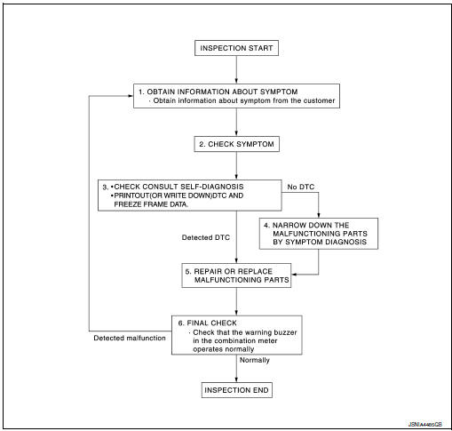
Work Flow
OVERALL SEQUENCE
DETAILED FLOW
1.OBTAIN INFORMATION ABOUT SYMPTOM
Interview the customer to obtain as much information as possible about the conditions and environment under which the malfunction occurred.
>> GO TO 2.
2.CHECK SYMPTOM
- Check the symptom based on the information obtained from the customer.
- Check if any other malfunctions are present.
> GO TO 3.
3.CHECK CONSULT SELF-DIAGNOSIS RESULTS
- Connect CONSULT and perform "self-diagnosis". Refer to WCS-27, "DTC Index".
- When DTC is detected, follow the instructions below:
- Record DTC and Freeze Frame Data.
Are self-diagnosis results normal? YES >> GO TO 4.
NO >> GO TO 5.
4.NARROW DOWN MALFUNCTIONING PARTS BY SYMPTOM DIAGNOSIS
Perform symptom diagnosis and narrow down the malfunctioning parts.
>> GO TO 5.
5.REPAIR OR REPLACE MALFUNCTIONING PARTS
Repair or replace malfunctioning parts.
NOTE: If DTC is displayed, erase DTC after repairing or replacing malfunctioning parts.
>> GO TO 6.
6.FINAL CHECK
Check that the warning buzzer in the combination meter operates normally.
Does it operate normally? YES >> Inspection End.
NO >> GO TO 1.
 Wiring diagram
Wiring Diagram
...

Other materials:
Maintenance requirements
Your NISSAN is designed to have minimum maintenance
requirements with long service intervals
to save you both time and money. However, some
day-to-day and regular maintenance is essential
to maintain your NISSAN’s good mechanical
condition, as well as its emissions and engine
performance.
...
LDW system operation
LDW system operation
The LDW system operates above approximately
45 MPH (70 km/h).
When the vehicle approaches either the left or
the right of the traveling lane, the LDW system
will chime a sound and the LDW light on the
instrument panel will blink to alert the driver
The LDW system is ...
Fusible link inspection
How To Check
A melted fusible link can be detected either by visual inspection or by
feeling with finger tip. If its condition is
questionable, use circuit tester or test lamp.
Fusible link
With stop/start system
Without stop/start system*
*: Not applicable
CAUTION:
If ...
