Nissan Rogue Service Manual: ABS actuator and electric unit (control unit)
Exploded View
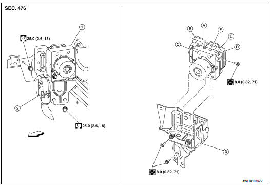
- ABS actuator and electric unit (control unit)
- Connector
- Bracket
- To front LH brake caliper
- To rear RH brake caliper
- From master cylinder secondary side
- From master cylinder primary side
- To rear LH brake caliper
- To front RH brake caliper
Removal and Installation
REMOVAL
CAUTION:
- To remove brake tube, use a flare nut wrench to prevent flare nuts and brake tube from being damaged.
- Do not remove actuator by holding harness.
NOTE: When removing components such as hoses, tubes/lines, etc., cap or plug openings to prevent fluid from spilling.
- Disconnect negative battery terminal. Refer to PG-75, "Exploded View".
- Remove the cowl top cover and cowl top extension. Refer to EXT-25, "Removal and Installation".
- Separate brake tubes from ABS actuator and electric unit (control unit). Refer to BR-22, "FRONT : Exploded View".
- Remove the brake booster vacuum hose. Refer to BR-32, "Removal and Installation".
- Separate the brake booster vacuum tube and place aside. Refer to BR-23, "FRONT : Removal and Installation".
- Disconnect the harness connector from the ABS actuator and electric unit (control unit).
- Remove ABS actuator and electric unit (control unit) bracket bolts and bushings.
- Remove ABS actuator and electric unit (control unit) from vehicle.
INSTALLATION
Installation is in the reverse order of removal.
- After work is completed, bleed air from brake tube. Refer to BR-16, "Bleeding Brake System".
- Adjust the neutral position of steering angle sensor. Refer to BRC-70, "Work Procedure".
- Perform calibration of the decel G sensor. Refer to BRC-72, "Work Procedure".
CAUTION:
- To install, use flare nut crowfoot and torque wrench.
- Do not reuse the bushings.
- Replace the ABS actuator if it has been dropped or sustained an impact.
- Do not install actuator by holding harness.
- After installing harness connector in the ABS actuator and electric unit (control unit), make sure connector is securely locked.
 Sensor rotor
FRONT SENSOR ROTOR
FRONT SENSOR ROTOR : Removal and Installation - Front Sensor Rotor
The front wheel sensor rotor is an integral part of the wheel hub and bearing
and cannot be disassembled.
R ...
 VDC off switch
Removal and Installation
REMOVAL
Remove the instrument lower panel LH. Refer to IP-14, "INSTRUMENT
PANEL ASSEMBLY : Removal
and Installation".
Release pawls using sui ...
Other materials:
DTC/circuit diagnosis
U1000 CAN COMM CIRCUIT
Description
Refer to LAN-8, "System Description".
DTC Logic
DTC DETECTION LOGIC
NOTE:
U1000 can be set if a module harness was disconnected and reconnected, perhaps
during a repair. Confirm
that there are actual CAN diagnostic symptoms and a present DTC by p ...
Warning/indicator lights and audible reminders
Anti-lock Braking System (ABS)
warning light
Brake warning light
Charge warning light
Low tire pressure warning light
Low windshield washer fluid warning light (if so
equipped)
Master warning light
Power s ...
Symptom diagnosis
HEATER AND AIR CONDITIONING SYSTEM CONTROL SYMPTOMS
Symptom Table
SYMPTOM TABLE
Symptom
Reference Page
A/C system does not come on.
Go to Trouble Diagnosis Procedure for A/C System.
HAC-166, "FRONT
A/C CONTROL : Diagnosis
Procedure"
Air ou ...
