Nissan Rogue Service Manual: System description
COMPONENT PARTS
Component Parts Location
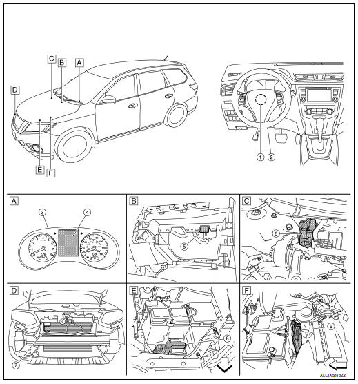
 Front of vehicle
- Instrument panel LH
- View with glove box removed
- Rear of engine compartment RH
- RH front of vehicle
- Front of engine compartment LH
- Rear of battery
|
No. |
Component parts |
Function |
| 1 | Function | BRC-14, "System Description" |
| 2 | Data link connector | LAN-26, "CAN COMMUNICATION SYSTEM : System Description" |
| 3 | Combination meter | MWI-8, "METER SYSTEM : System Description" |
| 4 | Vehicle information display | MWI-15, "INFORMATION DISPLAY : System Description" |
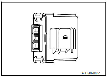
| 5 | Chassis control module | DAS-174, "Chassis Control Module" |
| 6 | ABS actuator and electric unit (control unit) | BRC-14, "System Description" |
| 7 | Distance sensor | DAS-16, "LDW : System Description" |
| 8 | Engine control module | EC-31, "ENGINE CONTROL SYSTEM : System Description" |
| 9 | Transmission control module | TM-31, "CVT CONTROL SYSTEM : System Description" |
Chassis Control Module
Chassis control module controls the following systems based on the signals from each sensor, switch, and control unit.
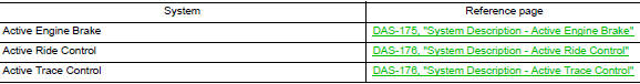
- Active engine brake
- Active ride control
- Active trace control
SYSTEM
System Description - Chassis Control
- Chassis control to integrally control the driving system was adopted.
- Chassis control module inputs the necessary information for control from CAN communication and each switch and integrally controls each system. Refer to the following table for systems controlled and input/output signals.
SYSTEM DIAGRAM
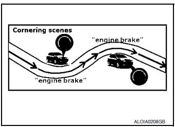
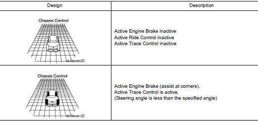
System Description - Active Engine Brake
Active Engine Brake function can be switched ON/OFF through the "Chassis Control" settings on the vehicle information display.
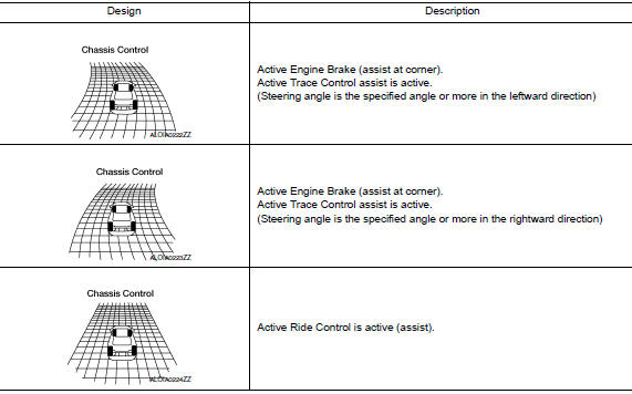
- Assist at corners - to lessen the workload of adjusting speed with brake pedal operations at corners. Active Engine Brake function adds small amount of deceleration by controlling the CVT gear ratio depending on the steering input and various sensors. This benefits to easier traceability at corners.
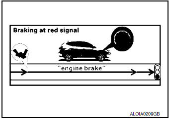
- Assist at breaking - To enhance braking feel, Active Engine Brake adds deceleration by shifting the CVT gear ratio to lower side depending on the driver’s brake pedal operation.
System Description - Active Ride Control
The Active Ride Control function can be turned ON/OFF by turning the VDC OFF switch ON/OFF.
- Engine control - Enhances ride comfort by adding/subtracting engine torque in an effort to control the front and rear wheel load balance.
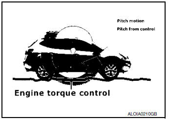
- Engine control - Enhances handling by adding/subtracting engine torque in an effort to control the front and rear wheel load balance.
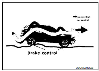
- Brake control - Enhances ride comfort by restraining upper body movement with small amount of brake control when driving on bumpy roads.
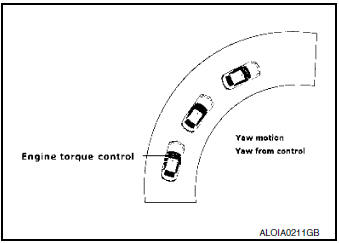
System Description - Active Trace Control
Active Trace Control function controls the braking utilizing the ABS actuator and electric unit (control unit), depending on cornering condition calculated from driver’s steering input and plural sensors. Active Trace Control function is aimed to enhance traceability at corners and smooth the vehicle movement to provide confident driving.
Active Trace Control function can be switched ON/OFF through the "Chassis Control" settings on the vehicle information display. When the Active Trace Control is selected OFF, some functions will be kept ON to assist driver (for example, avoidance condition).
When the VDC OFF switch is used to turn OFF the VDC system, the Active Trace Control system is also completely turned OFF.
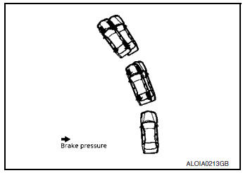
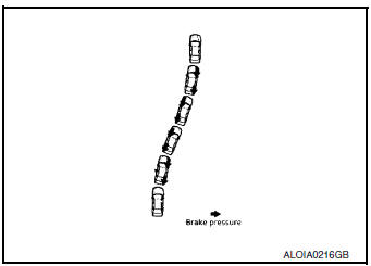
- Steady cornering - The change of forward and lateral acceleration is smoothened by applying the necessary amount of brake pressure.
- Transient steering input - Reduces lag of yaw rate against steering operation.
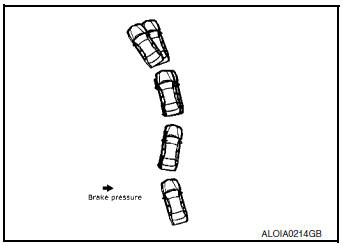
- Acceleration at corners - Restrains understeer by applying the necessary amount of brake pressure to the inner wheels.
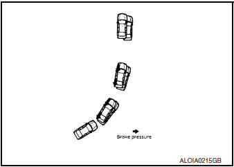
- Quick lane change - achieves stable vehicle behavior at quick steering operation by applying the necessary amount of brake pressure to the appropriate wheels.
Fail-Safe (Chassis Control Module)
- When chassis control module detects an error in the chassis control system architecture (including other system components), the master warning lamp turns ON and an interrupt is displayed on the information display of the combination meter. Please check the DTCs and investigate the cause of error.
INFORMATION DISPLAY (COMBINATION METER)
INFORMATION DISPLAY (COMBINATION METER) : Chassis Control Display
DESIGN/PURPOSE
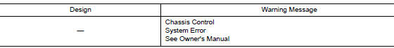
- The warning message is displayed on the vehicle information display when chassis control module detects an error in the chassis control system architecture. Please check the DTCs and investigate the cause of error.
- Each chassis control system information is displayed on the vehicle information display.
Warning Message
System Information
Indicator operating
- Active Engine Brake: Refer to DAS-175, "System Description - Active Engine Brake".
- Active Ride Control: Refer to DAS-176, "System Description - Active Ride Control".
- Active Trace Control: Refer to DAS-176, "System Description - Active Trace Control".
HANDLING PRECAUTION
Precautions for Chassis Control (Engine Brake, Active Ride, and Active Trace)
CHASSIS CONTROL
- Chassis Control will not provide all the necessary controls to replace driver intervention. It is not designed to prevent loss of control. It is the driver’s responsibility to stay alert, drive safely, keep the vehicle in the traveling lane, and be in control of vehicle at all times.
- Chassis Control is primarily intended for use on well-developed freeways or highways. It may not perform satisfactorily in certain roads, weather or driving conditions.
- Using Chassis Control under some conditions of road, corner or severe weather could lead to an unexpected system operation. In such conditions, driver needs to correct the vehicle's direction with driver's steering operation to avoid accidents.
- When Chassis Control is operating, avoid excessive or sudden steering maneuvers. Otherwise, you could lose control of the vehicle.
- Engine Brake Control is designed to enhance braking feel and traceability at corners.
- Active Ride Control is designed to enhance handling and drive comfort.
- Active Trace Control is designed to enhance traceability at corners and smooth vehicle movement for more confident driving.
- Chassis Control may not function properly under the following conditions:
- During bad weather (rain, fog, snow, wind, etc.).
- When driving on slippery roads, such as on ice or snow, etc.
- When driving on winding or uneven roads.
- When driving with a tire that is not within normal tire conditions (for example, tire wear, low tire pressure, installation of spare tire, tire chains, non-standard wheels).
- When the vehicle is equipped with non-original steering parts or suspension parts.
- The functions of Chassis Control may or may not operate properly under the following conditions:
- On roads covered with water, dirt or snow, etc.
- On roads where there are sharp curves.
DIAGNOSIS SYSTEM (CHASSIS CONTROL MODULE)
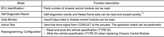
CONSULT Function
APPLICATION ITEM
CONSULT can display each diagnostic item using the diagnostic test modes as follows.
*1: The following diagnosis information is erased by erasing.
- DTC
- Freeze frame data (FFD)
ECU IDENTIFICATION
Chassis control module part number can be read.
SELF DIAGNOSTIC RESULT
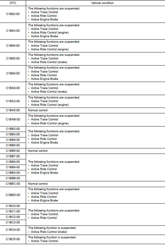
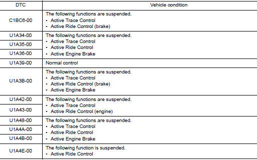
Refer to DAS-194, "DTC Index".
When “CRNT” is displayed on “self-diagnosis result”
- The system is presently malfunctioning.
When “PAST” is displayed on “self-diagnosis result”
- System malfunction in the past is detected, but the system is presently normal.
Freeze frame data (FFD)
When DTC is detected, a vehicle state shown below is recorded and displayed on CONSULT.
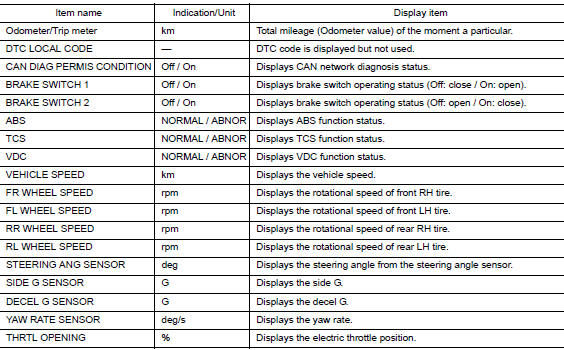
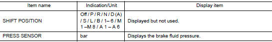
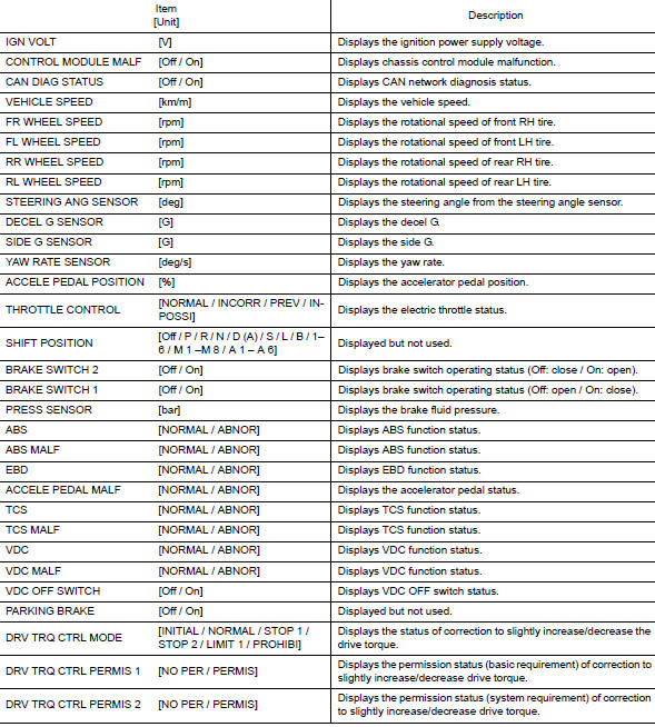
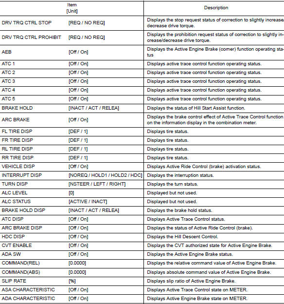
DATA MONITOR
NOTE: The following table includes information (items) inapplicable to this vehicle. For information (items) applicable to this vehicle, refer to CONSULT display items.
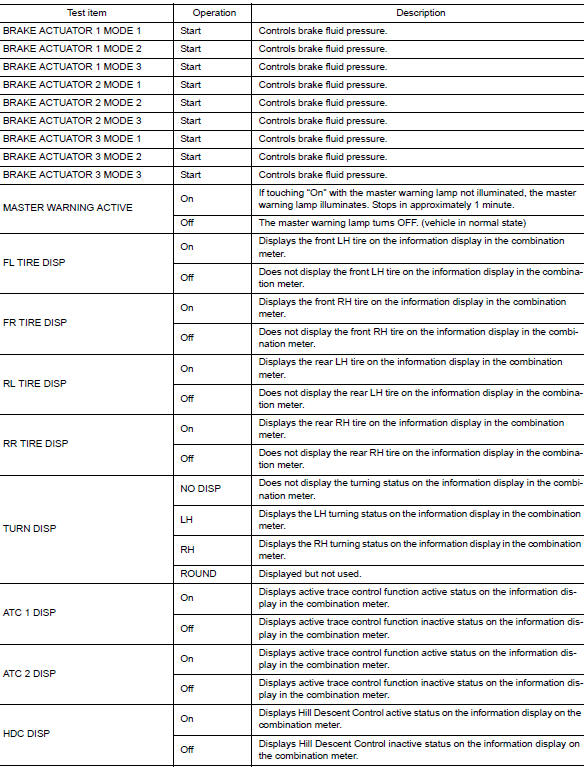
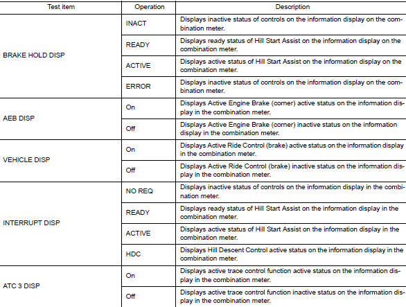
ACTIVE TEST
The active test is used to determine and identify details of a malfunction, based on self-diagnosis test results and data obtained in the DATA MONITOR. In response to instructions from CONSULT, instead of those from chassis control module on the vehicle, a drive signal is sent to the actuator to check its operation.
CAUTION:
- Never perform ACTIVE TEST while driving the vehicle.
- Always bleed air from brake system before active test.
- Never perform active test when system is malfunctioning.
NOTE:
- When active test is performed while depressing the brake pedal, the brake pedal depressing stroke may change. This is not a malfunction.
- During an active test, sometimes a chassis control warning is displayed and the master warning lamp illuminates on the information display in the combination meter; however, this is not a malfunction.
RE/PROGRAMMING, CONFIGURATION
Configuration includes the following functions.
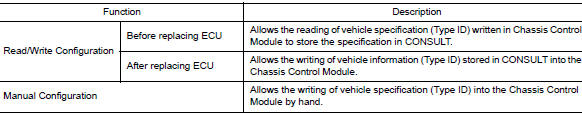
CAUTION: Use “Manual Configuration” only when “TYPE ID” of Chassis Control Module cannot be read.
 Preparation
Special Service Tool
The actual shape of the tools may differ from those illustrated here.
Tool number
(TechMate No.)
Tool name
Description
—
(J-46534)
Trim ...
 ECU diagnosis information
CHASSIS CONTROL MODULE
Reference Value
CONSULT DATA MONITOR STANDARD VALUE
NOTE:
The following table includes information (items) inapplicable to this vehicle.
For information (items) applicable ...
Other materials:
Rapid air pressure loss
Rapid air pressure loss or a “blow-out” can occur
if the tire is punctured or is damaged due to
hitting a curb or pothole. Rapid air pressure loss
can also be caused by driving on under-inflated
tires.
Rapid air pressure loss can affect the handling
and stability of the vehicle, especial ...
Changing wheels and tires
Tire rotation
NISSAN recommends rotating the tires
every 7,500 miles (12,000 km).
Refer to “Flat tire” in the “In case of emergency”
section in this manual for tire replacing
procedures.
As soon as possible, tighten the
wheel nuts to the specified torque
with a torque wrench.
...
Rocker cover
Oil filler cap
Rocker cover
Rocker cover gasket
Refer to INSTALLATION
Engine front
Removal and Installation
REMOVAL
Remove intake manifold. Refer to EM-26, "Removal and
Installation".
Remove wheel and tire (RH) using a power to ...
