Nissan Rogue Service Manual: Shift lock system
Component Function Check
1.CHECK SHIFT LOCK OPERATION (PART 1)
- Turn ignition ON.
- Shift the selector lever to “P” position.
- Attempt to shift the selector lever to any other than position with the brake pedal released.
Can the selector lever be shifted to any other position? YES >> Go to TM-183, "Diagnosis Procedure".
NO >> GO TO 2.
2.CHECK SHIFT LOCK OPERATION (PART 2)
Attempt to shift the selector lever to any other than position with the brake pedal depressed.
Can the selector lever be shifted to any other position? YES >> Inspection End.
NO >> Go to TM-183, "Diagnosis Procedure".
Diagnosis Procedure
Regarding Wiring Diagram information, refer to TM-75, "Wiring Diagram".
1.CHECK STOP LAMP SWITCH
- Ignition switch ON.
- Check voltage between stop lamp switch connector E38 terminal 4 and ground.
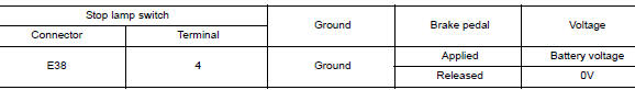
Is the inspection result normal? YES >> GO TO 2.
NO >> GO TO 4.
2.CHECK CVT SHIFT SELECTOR
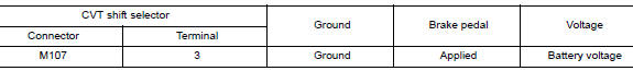
Check voltage between CVT shift selector connector M107 terminal 4 and ground.
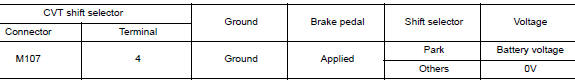
Is the inspection result normal? YES >> GO TO 3.
NO >> GO TO 5.
3.CHECK GROUND CIRCUIT
- Ignition switch OFF.
- Disconnect CVT shift selector connector.
- Check continuity between CVT shift selector connector M107 terminal 4 and ground.
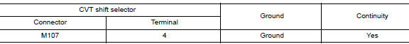
Is the inspection result normal? YES >> Replace CVT shift selector. Refer to TM-194, "Removal and Installation".
NO >> Repair or replace harness.
4.CHECK STOP LAMP SWITCH POWER CIRCUIT
Check voltage between stop lamp switch connector E38 terminal 3 and ground.
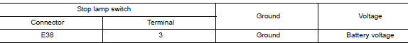
Is the inspection result normal? YES >> Replace stop lamp switch. Refer to BR-20, "Exploded View".
NO >> Repair or replace harness.
5.CHECK CVT SHIFT SELECTOR POWER CIRCUIT
Check voltage between CVT shift selector connector M107 terminal 3 and ground.
Is the inspection result normal? YES >> Replace CVT shift selector. Refer to TM-194, "Removal and Installation".
NO >> Repair or replace harness or connector.
Component Inspection (CVT Shift Selector Assembly)
1.CHECK CVT SHIFT SELECTOR ASSEMBLY (PART 1)
Check continuity between CVT shift selector connector terminals.
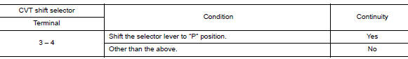
Is the inspection result normal? YES >> GO TO 2.
NO >> Replace CVT shift selector assembly. Refer to TM-194, "Removal and Installation".
2.CHECK CVT SHIFT SELECTOR ASSEMBLY (PART 2)
Apply voltage to terminals of CVT shift selector and check that shift lock solenoid is activated.
CAUTION:
- Connect the fuse between the terminals when applying the voltage.
- Never cause shorting between terminals.
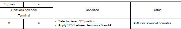
Is the inspection result normal? YES >> Inspection End NO >> Replace CVT shift selector assembly. Refer to TM-194, "Removal and Installation".
Component Inspection (Stop Lamp Switch)
1.CHECK STOP LAMP SWITCH
Check continuity between the stop lamp switch connector terminals.
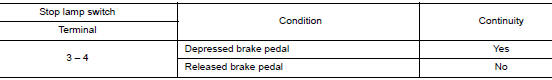
Is the inspection result normal? YES >> Inspection End.
NO >> Replace stop lamp switch. Refer to BR-20, "Exploded View".
 Shift position indicator circuit
Component Parts Function Inspection
1.CHECK SHIFT POSITION INDICATOR
Start the engine.
Shift selector lever.
Check that the selector lever position and the shift position
...
 Symptom diagnosis
CVT CONTROL SYSTEM
Symptom Table
The diagnosis item number indicates the order of check. Start checking
in the order from 1.
Perform diagnoses of symptom table 1 before symptom table 2 ...
Other materials:
Precaution
Precaution for Supplemental Restraint System (SRS) "AIR BAG" and "SEAT
BELT
PRE-TENSIONER"
The Supplemental Restraint System such as “AIR BAG” and “SEAT BELT PRE-TENSIONER”,
used along
with a front seat belt, helps to reduce the risk or severity of injury to the
...
Unbalance steering wheel turning force (torque variation)
Description
Unbalance steering wheel turning force (torque variation).
Diagnosis Procedure
1.PERFORM SELF-DIAGNOSIS
With CONSULT
Turn the ignition switch OFF to ON.
Perform “EPS” self-diagnosis.
Is any DTC detected?
YES >> Check the DTC. Refer to STC-13, "DTC ...
LATCH (Lower Anchors and Tethers for CHildren) System
LATCH system lower anchor locations - bench seat
Your vehicle is equipped with special anchor
points that are used with LATCH system compatible
child restraints. This system may also be
referred to as the ISOFIX or ISOFIX compatible
system. With this system, you do not have to use
a vehicl ...
