Nissan Rogue Service Manual: Periodic maintenance
Introduction of Periodic Maintenance
The following tables show the normal maintenance schedule. Depending upon weather and atmospheric conditions, varying road surfaces, individual driving habits and vehicle usage, additional or more frequent maintenance may be required.
Periodic maintenance beyond the last period shown on the tables requires similar maintenance.
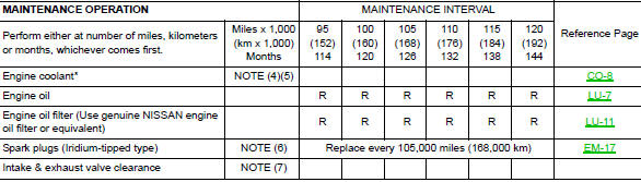
ENGINE AND EMISSION CONTROL MAINTENANCE
Abbreviations: R = Replace, I = Inspect and correct or replace as necessary
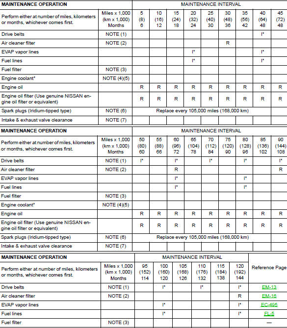
NOTE:
- (1) After 40,000 miles (64,000 km) or 48 months, inspect every 10,000 miles (16,000 km) or 12 months. Replace the drive belts if found damaged.
- (2) If operating mainly in dusty conditions, more frequent maintenance may be required.
- (3) Maintenance-free item. For service procedures, refer to FL section.
- (4) First replacement interval is 105,000 miles (168,000 km) or 84 months. After first replacement, replace every 75,000 miles (120,000 km) or 60 months.
- (5) Use only Genuine NISSAN Long Life Antifreeze / Coolant (blue) or equivalent with proper mixture ratio of 50% antifreeze and 50% demineralized or distilled water. Mixing any other type of coolant or the use of non-distilled water will reduce the life expectancy of the factory-fill coolant.
- (6) Replace spark plug when the spark plug gap exceeds 1.4 mm (0.055 in), even if within specified periodic replacement mileage.
- (7) Periodic maintenance is not required. However, if valve noise increases, inspect valve clearance.
*: Maintenance items and intervals with “*” are recommended by NISSAN for reliable vehicle operation. The owner need not perform such maintenance in order to maintain the emission warranty or manufacturer recall liability. Other maintenance items and intervals are required.
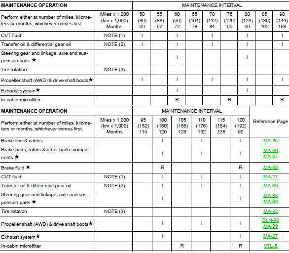
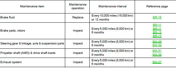
CHASSIS AND BODY MAINTENANCE
Abbreviations: R= Replace. I = Inspect. Correct or replace if necessary.
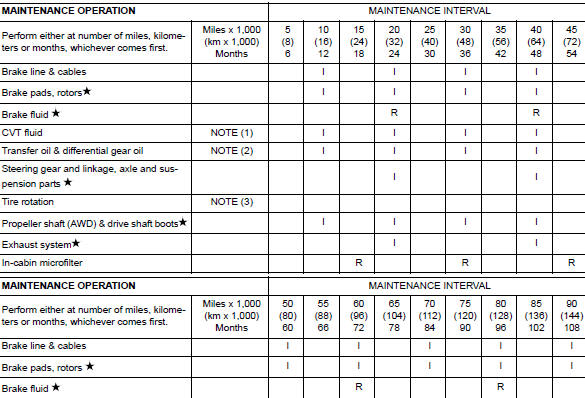
NOTE:
- Maintenance items with “ ” should be performed more frequently according to “Maintenance Under Severe Driving Conditions”.
- (1) Use only Genuine NISSAN CVT fluid. If towing a trailer, using a camper or a car-top carrier, of driving on rough or muddy roads, inspect CVT fluid deterioration at an NISSAN dealer every 60,000 miles (96,000 km), then change CVT fluid if necessary. And if the inspection is not performed, change (not just inspect) CVT fluid every 60,000 miles (96,000 km).
- (2) If tower a trailer, using a camper or car-top carrier, or driving on rough or muddy roads, change (not just inspect) oil at every 20,000 miles (32,000 km) or 24 months.
- (3) Refer to "Tire rotation" under "GENERAL MAINTENANCE" heading earlier in this section.
MAINTENANCE UNDER SEVERE DRIVING CONDITIONS
The maintenance intervals shown on the preceding pages are for normal operating conditions. If the vehicle is mainly operated under severe driving conditions as shown below, more frequent maintenance must be performed on the following items as shown in the table.
Severe driving conditions
- Repeated short trips of less than 5 miles (8 km).
- Repeated short trips of less than 10 miles (16 km) with outside temperatures remaining below freezing.
- Operating in hot weather in stop-and-go "rush hour" traffic.
- Extensive idling and/or low speed driving for long distances, such as police, taxi or door-to-door delivery use.
- Driving in dusty conditions.
- Driving on rough, muddy, or salt spread roads.
- Towing a trailer, using a camper or a car-top carrier
Maintenance operation: Check = Check and correct or replace as necessary.
 General maintenance
Explanation of General Maintenance
General maintenance includes those items which should be checked during the
normal day-to-day operation
of the vehicle. They are essential if the vehicle is to c ...
 Recommended fluids and lubricants
Fluids and Lubricants
*1: For additional information, see “Engine Oil Recommendation”.
*2: As an alternative to this recommended oil, SAE 5W-30 conventional petroleum
based oil may be us ...
Other materials:
P0137 HO2S2
DTC Description
DTC DETECTION LOGIC
The heated oxygen sensor 2 has a much longer switching time
between rich and lean than the air fuel ratio (A/F) sensor 1. The oxygen
storage capacity of the three way catalyst (manifold) causes the
longer switching time. To judge the malfunctions of heated ox ...
Precaution
Precaution for Supplemental Restraint System (SRS) "AIR BAG" and "SEAT
BELT
PRE-TENSIONER"
The Supplemental Restraint System such as “AIR BAG” and “SEAT BELT PRE-TENSIONER”,
used along
with a front seat belt, helps to reduce the risk or severity of injury to the
...
Parking brake switch
Removal and Installation
REMOVAL
Remove the instrument lower panel LH. Refer to IP-22, "Removal and
Installation".
Disconnect the harness connector from the parking brake switch.
Refer to PB-7, "Exploded View".
Remove the screw and remove the park ...
