Nissan Rogue Service Manual: Parking brake switch
Component Function Check
1.CHECK PARKING BRAKE SWITCH OPERATION
Check that brake warning lamp in combination meter turns ON/OFF when parking brake is operated.
Is the inspection result normal? YES >> Inspection End.
NO >> Proceed to BRC-115, "Diagnosis Procedure".
Diagnosis Procedure
1.CHECK PARKING BRAKE SWITCH CIRCUIT
- Turn the ignition switch OFF.
- Disconnect parking brake switch harness connector.
- Disconnect combination meter harness connector.
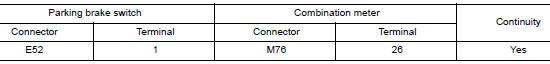
- Check the continuity between parking brake switch harness connector and combination meter harness connector.
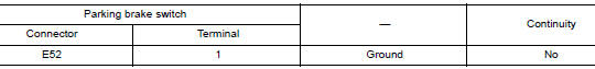
- Check the continuity between parking brake switch harness connector and ground.
Is the inspection result normal? YES >> GO TO 2.
NO >> Repair or replace error-detected parts.
2.CHECK PARKING BRAKE SWITCH
Check the parking brake switch. Refer to PB-4, "Inspection and Adjustment".
Is the inspection result normal? YES >> GO TO 3.
NO >> Replace the parking brake switch. Refer to PB-7, "Exploded View".
3.CHECK PARKING BRAKE SWITCH SIGNAL
 With CONSULT
- Connect parking brake switch harness connector.
- Connect combination meter harness connector.
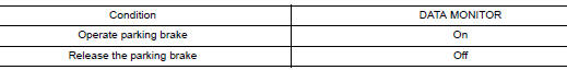
- Select “ABS”, “DATA MONITOR” and “PARK BRAKE SW” according to this order. Check the parking brake switch signal.
Is the inspection result normal? YES >> Inspection End.
NO >> GO TO 4.
4.CHECK COMBINATION METER
Check the combination meter. Refer to MWI-21, "CONSULT Function (METER/M&A)".
Is the inspection result normal? YES >> GO TO 5.
NO >> Repair or replace combination meter. Refer to MWI-82, "Removal and Installation".
5.CHECK TERMINAL
- Check the combination meter pin terminals for damage or loose connection with harness connector.
- Check the parking brake switch pin terminals for damage or loose connection with harness connector.
Is the inspection result normal? YES >> Replace the ABS actuator and electric unit (control unit). Refer to BRC-136, "Removal and Installation".
NO >> Repair or replace error-detected parts.
Component Inspection
1.CHECK PARKING BRAKE SWITCH
- Turn the ignition switch OFF.
- Disconnect parking brake switch harness connector.
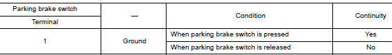
- Check the continuity between parking brake switch terminal and ground.
Is the inspection result normal? YES >> Inspection End.
NO >> Replace the parking brake switch. Refer to PB-7, "Exploded View".
 Power supply and ground circuit
Diagnosis Procedure
Regarding Wiring Diagram information, refer to PCS-24, "Wiring Diagram".
1. CHECK FUSE AND FUSIBLE LINKS
Check that the following IPDM E/R fuse or fusible links are no ...
 VDC off switch
Component Function Check
1.CHECK VDC OFF SWITCH OPERATION
Check that VDC OFF indicator lamp in combination meter turns ON/OFF when VDC
OFF switch is operated.
Is the inspection result normal?
...
Other materials:
U0101 CAN comm circuit
Description
CAN (Controller Area Network) is a serial communication line for real time
application. It is an on-vehicle multiplex
communication line with high data communication speed and excellent error
detection ability. Many electronic
control units are equipped onto a vehicle, and each co ...
P0863 TCM communication
DTC Description
DTC DETECTION LOGIC
DTC
CONSULT screen terms
(Trouble diagnosis content)
DTC detection condition
P0863
CONTROL UNIT (CAN)
(TCM Communication Circuit)
An error is detected at the initial CAN diagnosis of TCM.
POSSIBLE CAUSE
TCM
FAIL-SAFE
...
Wheel and tire
Adjustment
BALANCING WHEELS (ADHESIVE WEIGHT TYPE)
Preparation Before Adjustment
Remove inner and outer balance weights from the wheel. Using releasing agent,
remove double-faced adhesive
tape from the wheel and tire.
CAUTION:
Be careful not to scratch the wheel and tire during remo ...
