Nissan Rogue Service Manual: Parking brake front cable
Removal and Installation
REMOVAL
- Remove the instrument lower panel LH. Refer to IP-22, "Removal and Installation".
- Remove driver seat (LH). Refer to SE-32, "DRIVER SIDE : Removal and Installation"
- Remove the center console. Refer to IP-18, "Removal and Installation".
- Remove the parking brake control. Refer to PB-7, "Removal and Installation"
- Remove front door welts (LH). Refer to INT-23, "BODY SIDE WELT : Removal and Installation - Front Door Welt".
- Remove dash side finisher (LH). Refer to INT-24, "DASH SIDE FINISHER : Removal and Installation".
- Remove shift selector. Refer to TM-194, "Removal and Installation".
- Remove the front floor connecting ducts (LH/RH). Refer to VTL-10, "FRONT FLOOR DUCT : Removal and Installation - Front Floor Connecting Duct".
- Remove the front floor duct. Refer to VTL-11, "FRONT FLOOR DUCT : Removal and Installation - Front Floor Duct"
- Remove the rear center ventilator duct. Refer to VTL-11, "REAR CENTER VENTILATOR DUCT : Removal and Installation".
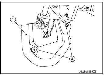
- Release clips (A) using a suitable tool and remove steering joint floor cover (1).
- Place front floor trim aside and remove the front floor spacer. Refer to INT-26, "Exploded View".
- Remove the bolts from the parking brake front cable mount. Refer to PB-7, "Exploded View".
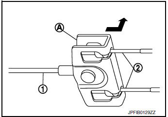
- Pull equalizer (A) of the parking brake front cable (1) in a
rearward
direction and then push upward to separate each parking
brake rear cable (2) from the parking brake front cable (1).
CAUTION: To prevent damage to the parts, do not bend the parking brake cables.
- Remove the parking brake front cable.
INSTALLATION
Installation is in the reverse order of removal.
CAUTION: Do not reuse the adjusting nut.
- Inspect and adjust the parking brake pedal. Refer to PB-4, "Inspection and Adjustment".
 Parking brake control
Exploded View
Parking brake rear cable (RH)
Parking brake rear cable (LH)
Parking brake front cable
Parking brake control
Adjusting nut
Parking brake switch
Removal and ...
 Parking brake rear cable
Removal and Installation
REMOVAL
Remove the center console assembly. Refer to IP-18, "Removal and
Installation".
Remove shift selector. Refer to TM-194, "Removal a ...
Other materials:
Rear LH side power window does not operate
WITH BOTH POWER WINDOW MAIN SWITCH AND REAR POWER WINDOW
SWITCH LH
WITH BOTH POWER WINDOW MAIN SWITCH AND REAR POWER WINDOW
SWITCH LH : Diagnosis Procedur
1.CHECK REAR POWER WINDOW SWITCH
Check rear power window switch.
Refer to PWC-36, "Component Function Check".
Is the inspect ...
General maintenance
During the normal day-to-day operation of the
vehicle, general maintenance should be performed
regularly as prescribed in this section. If
you detect any unusual sounds, vibrations or
smells, be sure to check for the cause or have a
NISSAN dealer do it promptly. In addition, you
should notify ...
Front power seat adjustment (if so equipped)
Operating tips
The power seat motor has an auto-reset
overload protection circuit. If the motor
stops during operation, wait 30 seconds
then reactivate the switch.
Do not operate the power seat switch for a
long period of time when the engine is off.
This will dischar ...
