Nissan Rogue Service Manual: P2815 select solenoid
DTC Description
DTC DETECTION LOGIC
| DTC | CONSULT screen terms (Trouble diagnosis content) | DTC detection condition |
| P2815 | SELECT SOLENOID (Select solenoid) | When all of the following conditions are satisfied and this state is
maintained
for 0.2 seconds:
|
POSSIBLE CAUSE
- Harness or connector (Select solenoid valve circuit open or shorted to power supply)
- Select solenoid valve
FAIL-SAFE
Selector shock is large
DTC CONFIRMATION PROCEDURE
1.PREPARATION BEFORE WORK
If another "DTC CONFIRMATION PROCEDURE" occurs just before, turn ignition switch OFF and wait for at least 10 seconds, then perform the next test.
>> GO TO 2.
2.CHECK DTC DETECTION
- Start the engine.
- Maintain the following conditions. (Keep 5 seconds or more after the selector lever shifted.)
Selector lever : N → D, N → R, P → R
- Check the first trip DTC.
Is “P2815” detected? YES >> Go to TM-174, "Diagnosis Procedure".
NO-1 >> To check malfunction symptom before repair: Refer to GI-41, "Intermittent Incident".
NO-2 >> Confirmation after repair: INSPECTION END
Diagnosis Procedure
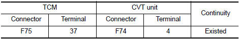
1.CHECK CIRCUIT BETWEEN TCM AND CVT UNIT
- Turn ignition switch OFF.
- Disconnect TCM connector and CVT unit connector.
- Check continuity between TCM harness connector terminal and ground.
Is the inspection result normal? YES >> GO TO 2.
NO >> Repair or replace damaged parts.
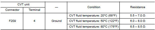
2.CHECK CIRCUIT BETWEEN CVT UNIT AND GROUND
Check continuity between CVT unit harness connector terminal and ground.
Is the inspection result normal? YES >> INSPECTION END
NO >> There is malfunction of select solenoid valve. Replace transaxle assembly. Refer to TM-220, "Removal and Installation".
 P2814 select solenoid
DTC Description
DTC DETECTION LOGIC
DTC
CONSULT screen terms
(Trouble diagnosis content)
DTC detection condition
P2814
SELECT SOLENOID
(Select solenoid)
When all of ...
 Main power supply and ground circuit
Diagnosis Procedure
1.CHECK TCM POWER CIRCUIT (PART 1)
Turn ignition switch OFF.
Disconnect TCM connector.
Check voltage between TCM harness connector terminals and ground.
...
Other materials:
Brake fluid
Drain and Refill
CAUTION:
Do not spill or splash brake fluid on painted surfaces. Brake
fluid may damage paint. If brake fluid is
splashed on painted areas, wash it away with water immediately.
Prior to repair, turn the ignition switch OFF, disconnect the
ABS actuator and ...
Precaution
Precaution for Supplemental Restraint System (SRS) "AIR BAG" and "SEAT
BELT
PRE-TENSIONER"
The Supplemental Restraint System such as “AIR BAG” and “SEAT BELT PRE-TENSIONER”,
used along
with a front seat belt, helps to reduce the risk or severity of injury to the
...
C1770, C1771, C1772, C1773 G sensor
DTC Description
DTC DETECTION LOGIC
DTC
Display Item
Malfunction Detected Condition
Possible Causes
C1770
G SENSOR FL
(G sensor front left)
Malfunction in the G sensor data from front left wheel sensor.
Tire pressure sensor
Tire pressure rece ...
