Nissan Rogue Service Manual: Interior room lamp control circuit
Description
Controls each interior room lamp (ground side) by PWM signal.
NOTE: PWM signal control period is approximately 250 Hz (in the gradual brightening/dimming).
Component Function Check
CAUTION: Before performing the diagnosis, check that the following is normal.
- Interior room lamp power supply
- Map lamp bulb
- Room lamp bulb
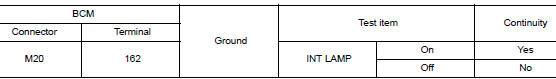
1.CHECK INTERIOR ROOM LAMP CONTROL FUNCTION
 CONSULT ACTIVE TEST
- Switch the map lamp switch and room lamp switch to DOOR.
- Turn power switch ON.
- Select ŌĆ£INT LAMPŌĆØ of ŌĆ£BCMŌĆØ active test item.
- With operating the test items, check that each interior room lamp turns ON/OFF (gradual brightening/dimming).
On : Interior room lamp gradual brightening
Off : Interior room lamp gradual dimming
Does the interior room lamp turns ON/OFF (gradual brightening/dimming)? YES >> Interior room lamp control circuit is normal.
NO >> Refer to INL-49, "Diagnosis Procedure".
Diagnosis Procedure
1.CHECK INTERIOR ROOM LAMP CONTROL OUTPUT
CONSULT ACTIVE TEST
- Turn power switch OFF.
- Remove all the bulbs of map lamp and room lamp.
- Turn power switch ON.
- Select ŌĆ£INT LAMPŌĆØ of ŌĆ£BCMŌĆØ active test item.
- With operating the test item, check continuity between BCM harness connector and ground.
Is the inspection result normal? YES >> GO TO 2.
Fixed ON>>GO TO 3.
Fixed OFF>>Replace BCM. Refer to BCS-75, "Removal and Installation" (with Intelligent Key system) or BCS-135, "Removal and Installation" (without Intelligent Key system).
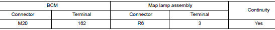
2.CHECK INTERIOR ROOM LAMP CONTROL OPEN CIRCUIT
- Turn power switch OFF.
- Disconnect BCM connector, map lamp assembly and room lamp connector.
- Check continuity between BCM harness connector and map lamp harness connector.
- Check continuity between BCM harness connector and room lamp harness connector.
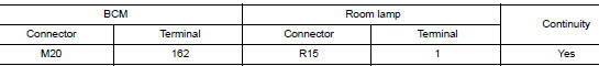
Is the inspection result normal? YES >> Replace map lamp or room lamp.
NO >> Repair or replace harnesses.
3.CHECK INTERIOR ROOM LAMP CONTROL SHORT CIRCUIT
- Turn power switch OFF.
- Disconnect BCM connector, map lamp connector and room lamp connector.
- Check continuity between BCM harness connector and ground.
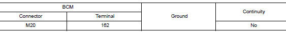
Is the inspection result normal? YES >> Replace BCM. Refer to BCS-75, "Removal and Installation" (with Intelligent Key system) or BCS- 135, "Removal and Installation" (without Intelligent Key system).
NO >> Repair or replace harnesses.
 Interior room lamp power supply circuit
Description
Provides the interior room lamp power supply. Also cuts the power supply when
the interior room lamp battery
saver is activating.
Component Function Check
1.CHECK INTERIOR ROOM LAMP ...
 Luggage room lamp circuit
Description
Controls the luggage room lamp (ground side) to turn the luggage room lamp ON
and OFF.
Diagnosis Procedure
CAUTION:
Before performing the diagnosis, check that the following is norma ...
Other materials:
Child safety
WARNINGDo not allow children to play with the seat
belts. Most seating positions are
equipped with Automatic Locking Retractor
(ALR) mode seat belts. If the seat belt
becomes wrapped around a childŌĆÖs neck
with the ALR mode activated, the child can
be seriously injured or k ...
Steering column
Inspection
HOLE COVER SEAL, HOLE COVER AND LOWER SHAFT
Check each part of hole cover seal, hole cover and steering column and lower
shaft for damage or other malfunctions.
Replace if necessary.
STEERING COLUMN
Check each part of steering column for damage or other
malfunctions. ...
Cluster lid C
Exploded View
Audio unit (AUDIO WITHOUT BOSE) /
AV control unit (AUDIO WITH BOSE)
(NAVIGATION WITH BOSE)
A/C switch assembly (AUTOMATIC
AIR CONDITIONING) / front air control
(MANUAL AIR CONDITIONING)
Cluster lid C
Removal and Installation
REMOVAL
Release ...
